 Kawasaki Z400 - Service manual > Steering
Exploded view
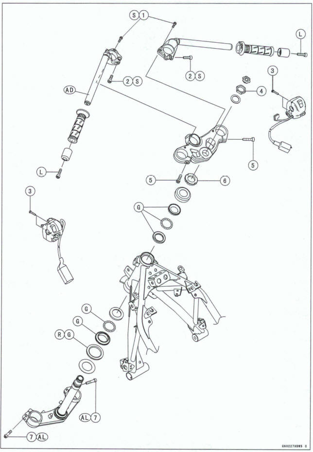
AD: Apply adhesive.
AL: Tighten the two damp bolts alternately two times to ensure tightening toque.
G: Apply grease.
L: Apply a non-permanent locking agent.
R: Replacement Parts
S: Follow the specified tightening sequence
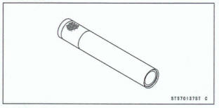
Bearing Puller Adapter: 57001 -136
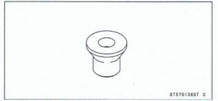
Stewing Stem Bearing Driver: 57001-137
Bearing Puller: 57001-158
Oil Seal & Bearing Remover:57001 -1 058
Oil Seal & Bearing Remover, Adapter B: 57001 -1 062
Steering Stem Bearing Driver Adapter,
 34.5 : 57001 -1 074
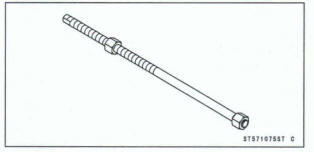
Head Pipe Outer Race Press Shaft: 57001-1075
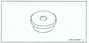
Head Pipe Outer Race Driver,  51.5:
57001-1076
51.5:
57001-1076
Steering Stem Nut Wrench: 57001-11 00
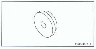
Head Pipe Outer Race Driver, 47:
57001 -1447
47:
57001 -1447
Bearing Puller: 57001 -1 575
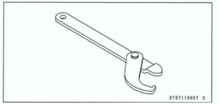
Adjustable Hook Wrench: 57001 -1883
Steering
Steering Inspection
- Refer to the Steering Play Inspection in the Periodic Maintenance chapter
Steering Adjustment
- Refer to the Steering Play Adjustment in the Periodic Maintenance chapter.
Steering Stem
Stem, Stem Bearing Removal
Remove: Upper Inner Cover (see Upper Inner Cover Removal in the Frame chapter) Front Forks (see Front Fork Removal in the Suspension chapter)
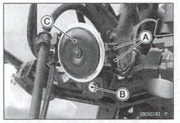
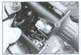
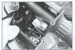
Disconnect the horn lead connectors [A].
Remove: Bolt [B] Horn [C]
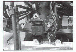
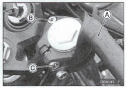
Remove the bolts [A].
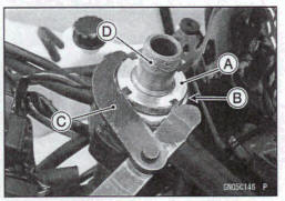
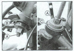
- Remove: Steering Stem Head Nut Plug [A] Steering Stem Head Nut [B] Washer [C]
- Move the stewing stem head aside
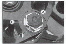
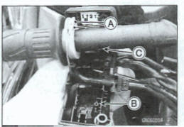
- Pushing up the stem base, and remove steering stem nut [A] and stem cap [B].
Special Tool - Steering Stem Nut Wrench [C]: 57001-1100
- Remove: Steering Stem [D]
Upper Ball bring Inner Race and Ball Bearings
NOTE
Be aware of removing the steering stem so that the stem bearing steel balls are not lost
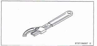
- You may move the steering stem nut using the adjustable hook wrench [A].
Special Tool - Adjustable Hook Wrench: 570014883
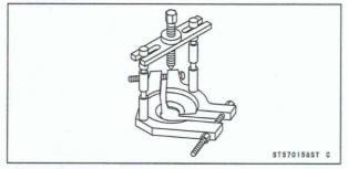
- Remove the upper and lower outer races using the remover [A].
Special Tools- Oil Seal & Bearing Remover: 57001-1058 Oil Seal & Bearing Remover, Adapter B: 57001 -1 062
NOTE
If either steering stem haring is damaged, it is recommended that both the upper and lower bearings (including outer races) should be replaced with new ones.
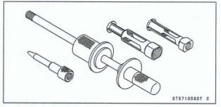
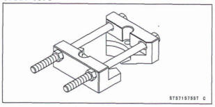
- Remove the lower ball bearing inner race [A] ( with its oil seal) which is pressed onto the steering stem using the bearing puller and adapter.
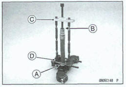
Special Tools - Bearing Puller Adaptor [B]: 57001-136
Baring Puller [C]: 57001-158
Bearing Puller [D]: 57001-1575
Stem, Stem Besting Installation
Replace, the bearing outer races with new ones.
Drive them into the head pipe at the same time.
Special Tools -Head Pipe Outer Race Press Shaft [A]:
57001 1075
Head Pipe Outer Race Driver,  51.5
[B]:
57001 -1076
Head Pipe Outer Race Driver, 47
[C]: 51001
-1447
51.5
[B]:
57001 -1076
Head Pipe Outer Race Driver, 47
[C]: 51001
-1447
- Replace the bearing inner races and oil seal with new ones.
- Apply greaser to the oil seal.
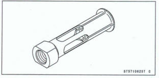
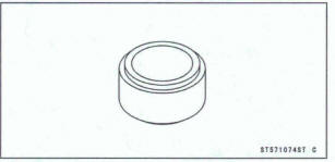
- Install the washer [A] and oil seal [B] on the steering stern, and drive the ball bearing inner race [C] applied grease onto the stem.
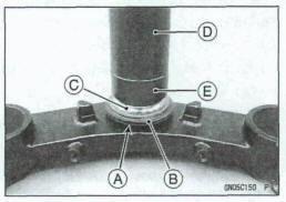
Special Tools- Steering Stem Bearing Driver [D]: 57001 -137
Steering Stem Bearing Driver Adapter,
 34.5 [E]: 57001-1074
- Apply grease to the inner races.
- Apply grease to the lower ball bearings (20) [A] and outer race, and install the ball bearings onto the outer race
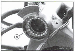
- Apply grease to the upper ball bearings (19) [A] and outer race, and install the ball bearings onto the outer race.
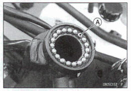
- Install the steering stem [A] carefully through the head pipe so that the steel balls on the head pipe does not fall.
- Apply grease to the upper ball bearing inner race and install it.
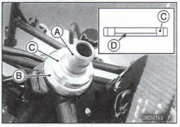
- Install the stem cap [B] and steering stem nut [C], and tighten it by hand.
- Install the steering stem nut with stepped side [D] facing down.
- Settle the bearings in place as follows.
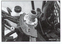
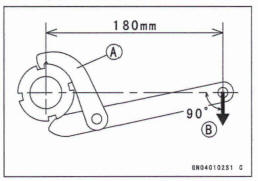
- Tighten the steering stem nut with 35 N-m (3.6 kgf-m, 26 ft-lb) of torque first (Pull the steering stem nut wrench [A] at the hole by 194 N (19.8 kgf) force [B] in the direction shown), and loosen it a fraction of a turn until it turns lightly. Afterward tighten it again with specified torque using the steering stem nut wrench.
- Check that there is no play and the steering stem turns smoothly without rattles. If not, the steering stem bearings may be damaged.
- You may tighten the steering stem nut using the adjustable hook wrench.
Special Tool - Steering Stern Nut Wrench: 57001-1100 or Adjustable Hook Wrench: 57001-1883
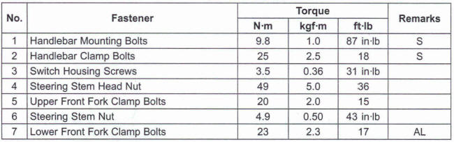
Torque - Steering Stem Nut: 4.9 N-m (0.50 kg*fm, 43 in-lb)
- Install the stem head [A].
- Install the washer [B], and tighten the stem head nut [C] temporarily.
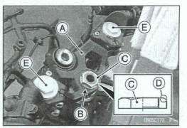
Install the stern nut with the chamfer side [D] facing up.
- Temporarily install the front forks [E] (see Front Fork Installation in the Suspension chapter).
- Tighten the stem head nut.
Torque -Steering Stem Head Nut: 40 N-m (5.0 kgf*m, 36 ft*lb)
- Reinstall the front forks (see Front Fork Installation in me Suspension chapter).
WARNING
If the handlebar does not turn to the steering stop it may cause an accident resulting in injury or death.
Be sure the cables, harnesses and hoses are routed properly and do not interfere, with handlebar movement (see Cable, Wire, and Hose Routing section in the Appendix chapter).
- Run the leads, wire harness and hoses correctly (see Cable, Wire, and Hose Routing section in the Appendix chapter).
- Install the removed parts (see appropriate chapters).
Steering Stem Beam Lubrication
- Refer to the Steering Stem Bearing Lubrication in the Periodic Maintenance chapter.
Steering Stem Warp Inspection
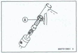
- Whenever the steering stem is removed, or if the steering can not be adjusted for smooth action, check the steering stem for straightness [A].
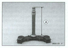
If the stewing stem is bent, replace it with a new one.
Handlebar Removal
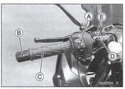
Remove: Left Switch Housing [A] Handlebar Weight [B] Left Handlebar Grip [C] Clutch Lever Holder Clamp Bolt [D] Clutch Lever Assembly [E]
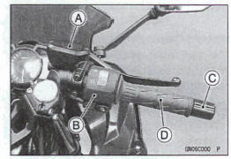
Remove: Front Master Cylinder [A] (see Front Master Cylinder Removal in the Brakes chapter) Right Switch Housing [B] Handlebar Weight [C] Throttle Grip [D]
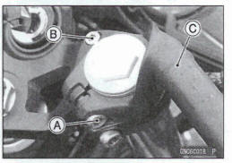
- Loosen the handlebar damp bolt [A].
- Remove: Handlebar Mounting Bolt [B] Handlebar [C]
Handlebar Installation
- Install the handlebar [A].
- Tighten the following bolts temporarily.
Handlebar Mounting Bolt [B] Handlebar Clamp Bolt [C]
- Tighten the handlebar mounting bolt first, and then the handlebar damp bolt
Torque -Handlebar Mounting Bolt: 9.8 N*m (1.0 kgf*m, 87 In*lb) Handlebar Clamp Bolt 25 N-m (2.5 kgf-m, 18 ft*lb)
- Install the clutch lever holder (see Clutch Lever Holder Installation in the Clutch chapter).
- Using a high flash-point solvent, clean off any oil or dirt that may be on the adhesive coating area. Dry them with a dean cloth.
- Apply adhesive cement to the handlebar, and install the left handlebar grip.
- Install the left switch housing.
Fit the projection [A] into a hole [B] in the handlebar.
- Tighten: Toque - Switch Housing Screws: 3.5 N*m (0.36 kern, 31 in-lb)
- Apply a non-permanent locking agent to the threads of the handlebar weight bolt.
- Install the right handlebar weight and tighten the handlebar weight bolt.
- Install: Front Master Cylinder (see Front Master Cylinder Installation in the Brakes chapter)
- Run the leads, cables and hoses correctly (see Cable, Wire, and Hose Routing section in the Appendix chapter).
- Install the removed parts (see appropriate chapters).
- Adjust the throttle grip free play (see Throttle Control System Inspection in the Periodic Maintenance chapter).
See also:
 Kawasaki Z400 - Service manual > TisRod, Rocker Ann
Tie-Rod Removal Squeeze the brake lever slowly and hold it with a band [A] Remove: Muffler Cover (see Muffler Removal in the Engine Top End Chapter) Loosen: Upper Tie- Rod Nut [A] Lower Tie-Rod Nut [B] Lower Rear Shock Absorber Nut [C] Rocker Arm Nut [D] Support the frame using the suitable stand Remove: Upper Tie-Rod Nut and Bolt Lower Rear Shock Absorber Nut and Bolt Rocker Arm Nut and Bolt Remove: Lower Tie-Rod Nut [A] and Bolt [B] Tie- Rods [C] Rocker Arm [D]
Kawasaki Z400 - Service manual > Frame
Exploded View
 Benelli Imperiale 400
 BMW F900XR
 Honda CB500X
 KTM 390 Adventure
 Triumph Street Triple S
 Yamaha MT-03
 Kawasaki Z400
 Triumph Street Triple S
 Yamaha MT-03