 Yamaha MT-03 - Service manual > Specifications
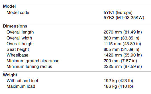
General specifications
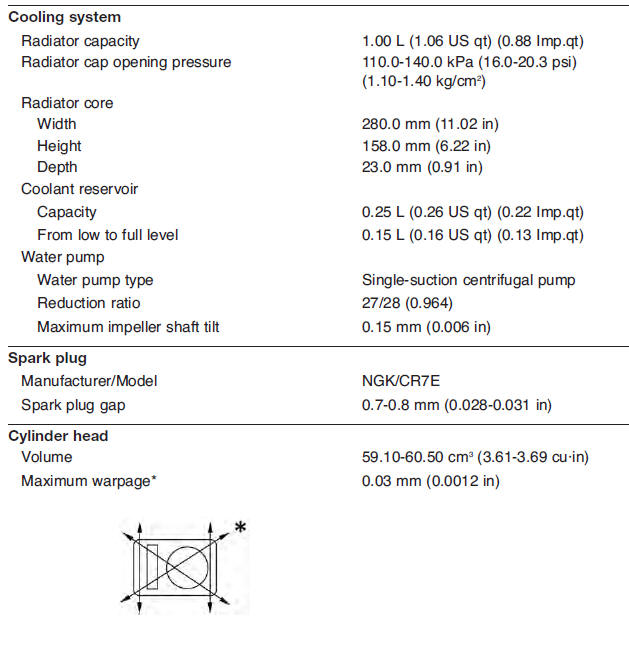
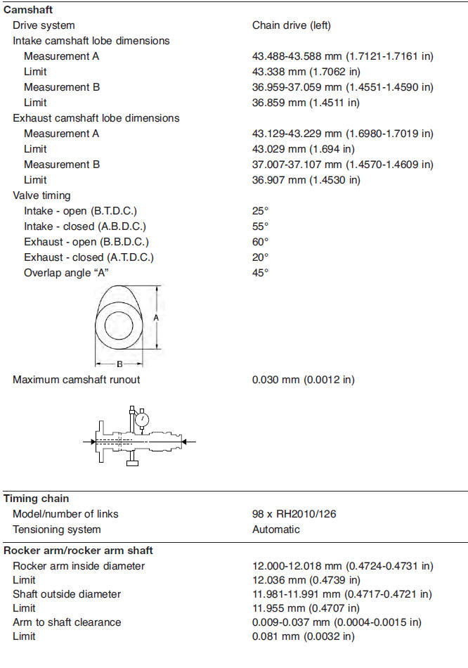
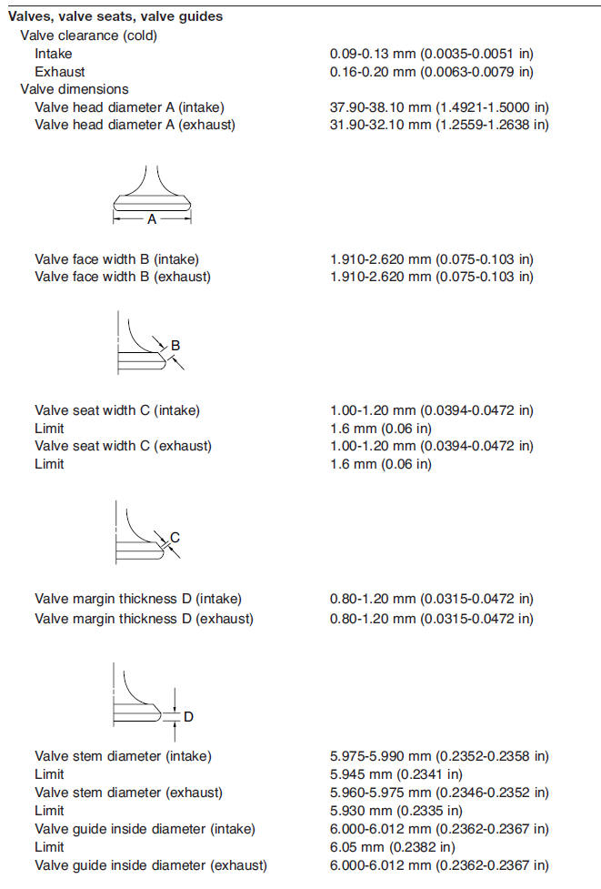
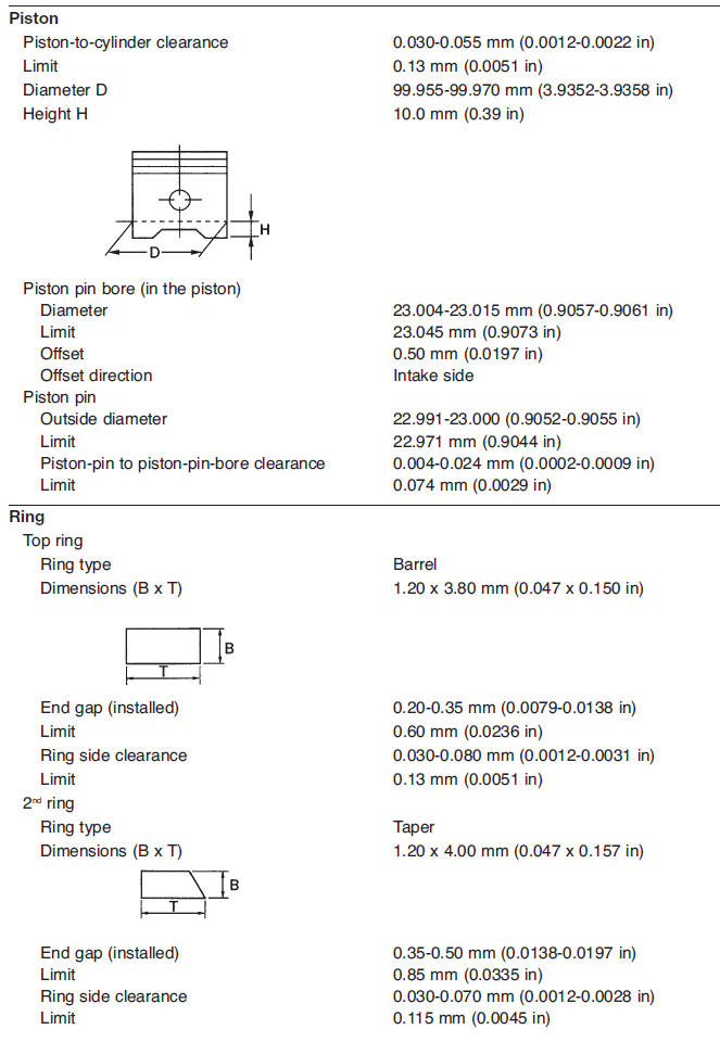
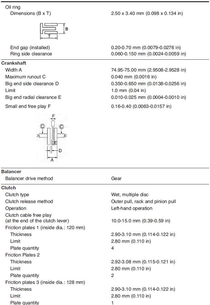
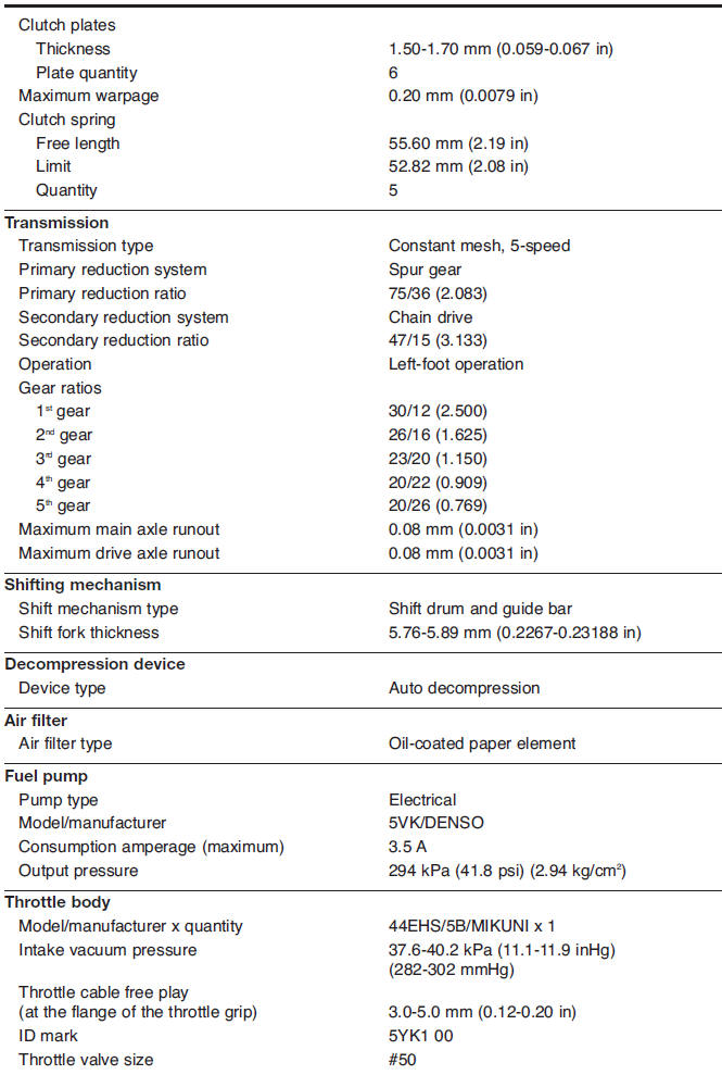
Engine specifications
y
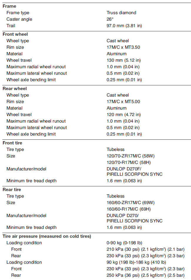
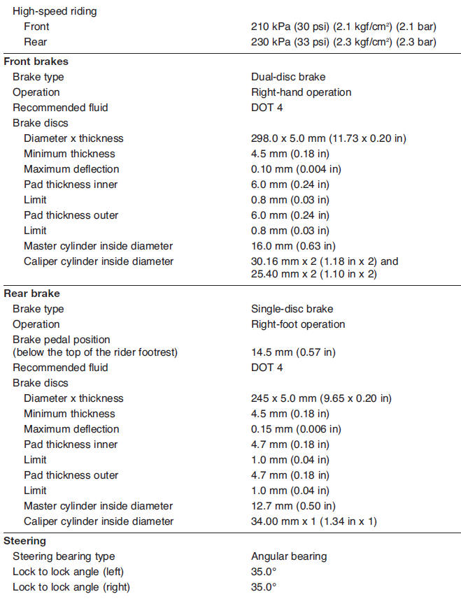
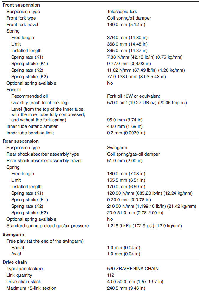
Chassis specifications
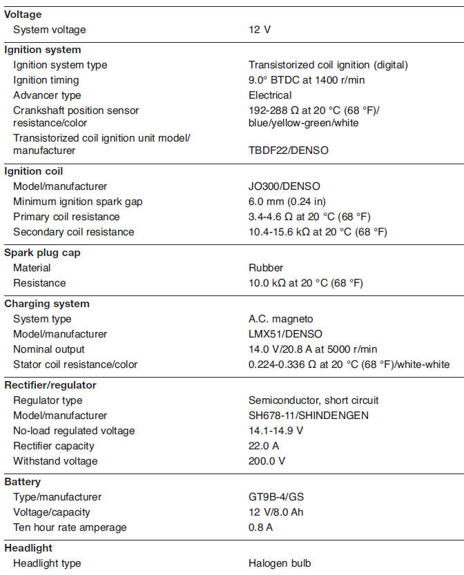
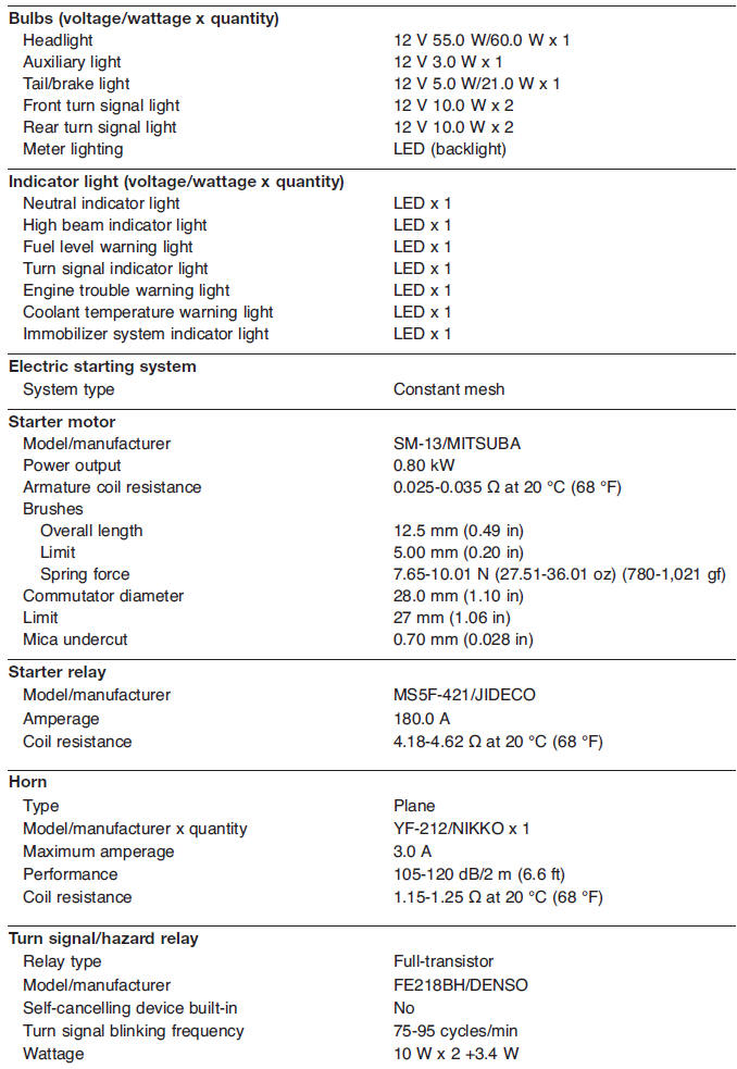
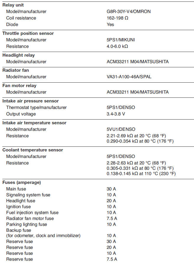
Electrical specifications
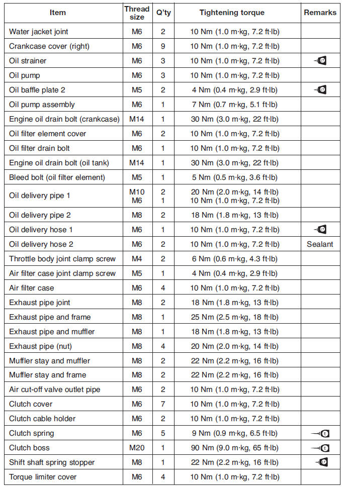
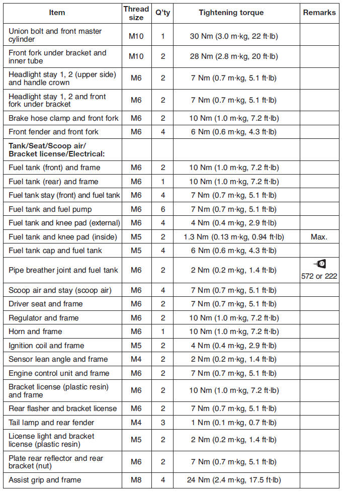
Tightening torques
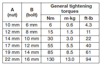
General tightening torque specifications
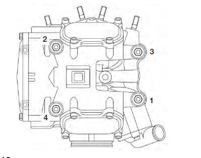
This chart specifies tightening torques for standard fasteners with a standard ISO thread pitch. Tightening torque specifications for special components or assemblies are provided for each chapter of this manual. To avoid war page, tighten multi-fastener assemblies in a crisscross pattern and progressive stages until the specified tightening torque is reached. Unless otherwise specified, tightening torque specifications require clean, dry threads. Components should be at room temperature.
- Distance between flats
- Outside thread diameter
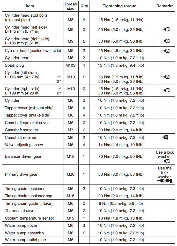
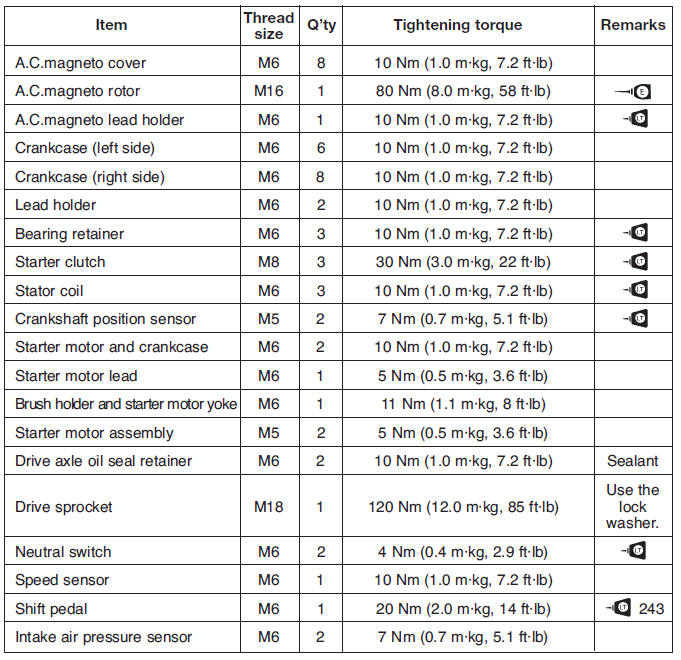
Engine tightening torques
Chassis tightening torques
Chassis tightening torques
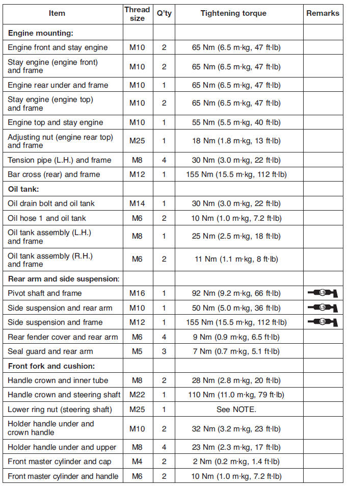
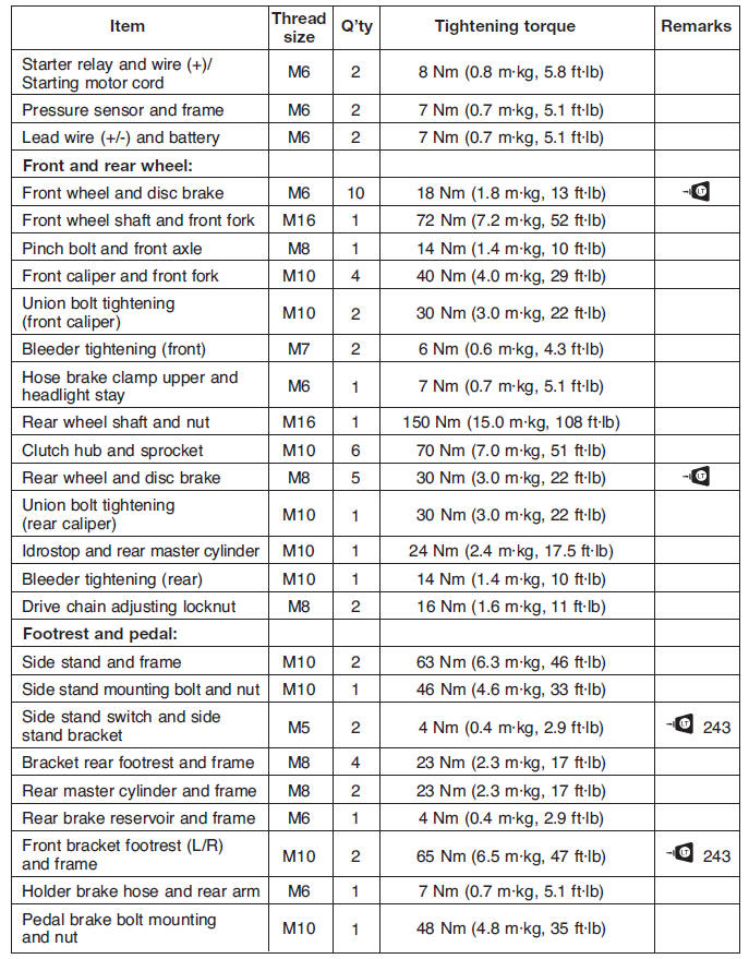
NOTE:
- First, tighten the lower ring nut approximately 52 Nm (5.2 m*kg, 38 ft*lb) by using the torque wrench, then loosen the ring nut completely.
- Retighten the lower ring nut 18 Nm (1.8 m*kg, 13 ft*lb) by using the torque wrench.
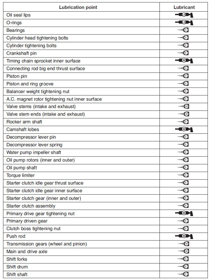
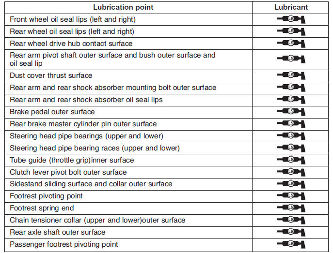
Lubrication points and lubricant types
Engine
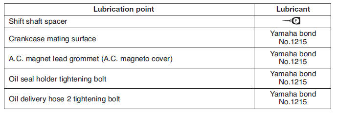
Chassis
Cooling system diagrams
- Water jacket joint
- Water pump outlet hose
- Water pump outlet pipe
- Water pump
- From the radiator
- To the cylinder
- Fast idle plunger outlet hose
- Coolant reservoir hose
- Coolant reservoir breather hose
- Radiator cap
- Radiator
- Coolant reservoir cap
- Coolant reservoir
- Radiator outlet hose
- Water pump
- Radiator fan
- Radiator inlet hose
- From the fast idle plunger
- To the cylinder
- From the thermostat
Lubrication chart
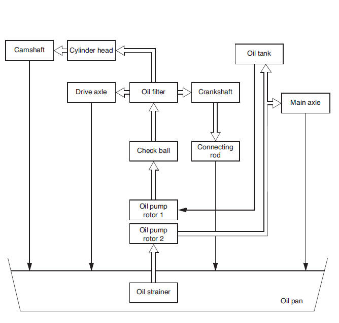
 Pressure feed
 Splashed scavenge
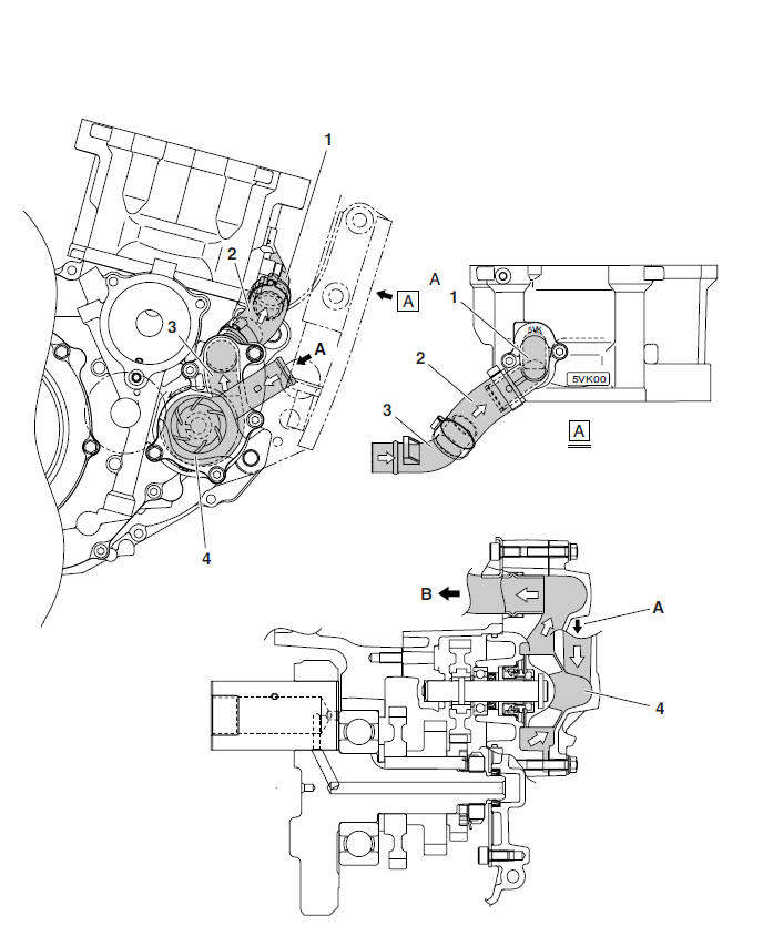
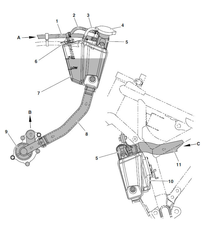
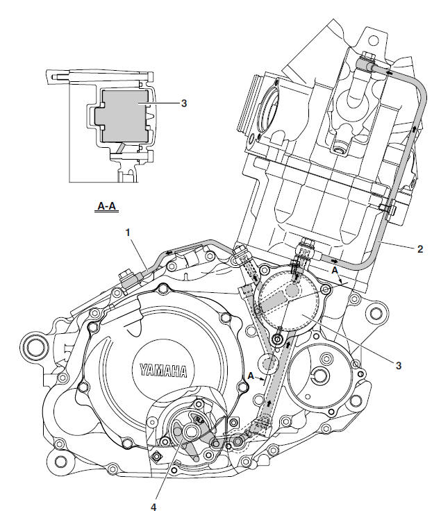
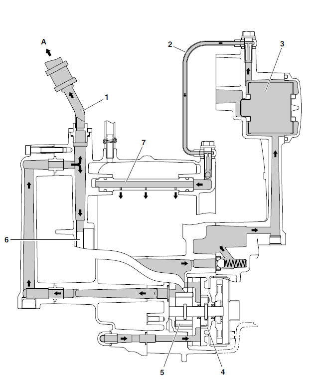
Lubrication diagrams
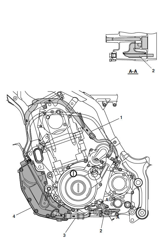
- Oil delivery hose 2
- Oil strainer
- Oil delivery hose 1
- Oil tank
- Oil delivery pipe 2
- Oil delivery pipe 1
- Oil filter
- Oil pump
- Oil delivery hose 2
- Oil delivery pipe 2
- Oil filter
- Oil pump rotor 1
- Oil pump rotor 2
- Main axle
- Oil delivery pipe 3
- To oil tank
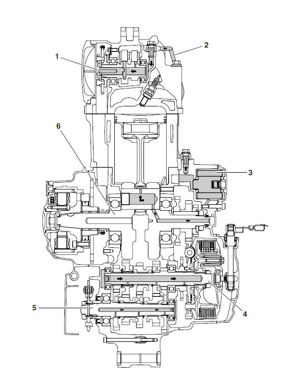
- Camshaft
- Oil delivery pipe 1
- Oil filter
- Main axle
- Drive axle
- Crankshaft
Cable routing
WARNING
Proper cable and lead routing are essential to insure safe motorcycle operation.
- Clutch cable
- Throttle cables
- Front brake hose
- Front brake light switch lead
- Plastic band
- Right handlebar switch lead
- Piece connecting and plastic band
- Clutch switch lead
- Fasten the right handlebar switch lead with a plastic band. Face the end of the plastic band forward.
- Fasten the right handlebar switch lead and front brake light switch lead with a plastic band. Face the end of the plastic band forward.
- Fasten the left handlebar switch lead and clutch switch lead with a plastic band. Face the end of the plastic band forward.
- Fasten the clutch cable with the piece connecting and plastic band. Face the end of the plastic band forward.
- Plastic band
- Front brake light switch lead
- Meter assembly lead
- Piece connecting and plastic band
- Clutch cable
- Clutch switch lead
- Left handlebar switch lead
- Front turn signal light coupler (left)
- Auxiliary light coupler
- Front brake hose holder
- Headlight coupler
- Front turn signal light coupler (right)
- Front brake hose
- Throttle cables
- Front brake hose holder
- Front brake hose
- Front fork under bracket
- Front brake caliper (left)
- Front brake caliper (right)
- Brake caliper projection
- Front mud guard
- When installing the brake hose onto the brake caliper, make sure that the brake pipe touches the projection on the brake caliper.
- Main switch
- Front brake light switch lead
- Plastic band
- Rear brake light switch coupler
- Spark plug lead
- Clutch cable
- Coolant temperature sensor lead
- Plastic band
- Intake air temperature sensor lead
- Intake air pressure sensor
- Throttle position sensor lead
- Fuel pump couplers
- Air induction system lead
- Battery
- Battery cover
- Negative battery lead
- Main switch couplers
- Immobilizer unit coupler
- Fasten the wire harness, negative battery lead and rear brake light switch lead to the frame with a plastic band.
- Plastic band
- Clutch cable
- Starter motor
- Negative battery lead
- Starter negative lead
- Rear brake pedal
- Rear brake light switch
- Rear brake master cylinder
- Rear brake hose
- Rear brake hose holder
- Rear brake caliper
- Main switch
- Positive battery lead
- Battery
- Battery cover
- Relay unit
- Starter relay
- Speed sensor lead
- Intake air pressure sensor
- Positive starter lead
- Horn lead
- Throttle cables
- Reserve fuse
- Main fuse
- Left handlebar switch lead
- Right handlebar switch lead
- Throttle cables
- ECU
- Lean angle cut-off switch
- Starter negative lead
- A.C. magneto lead
- Speed sensor
- Plastic band
- Rubber protection
- Rectifier/regulator
- Sidestand switch lead
- Neutral switch lead
- Starter motor
- Hose holder
- Main wire harness
- Speed sensor lead
- Wire holder
- Negative battery lead
- Negative coupler
- Fuel tank breather/overflow hoses
- Battery cover
- Plastic band
- Plastic locking tie
- Wire harness
- Speed sensor coupler
- ECU
- Fuel pump couplers
- Fuel injector lead
- Turn signal/hazard relay
- Headlight relay
- Radiator fan motor relay
- Fuel injection diagnostic tool coupler
- Anti-theft alarm coupler
- Fuse box
- Plastic band
- ECU
- Lean angle cut-off switch
- Extension wire harness
- Tail/brake light socket
- Rear turn signal light coupler (left)
- License plate light coupler
- Rear turn signal light coupler (right)
- Tail/brake light coupler
- Plastic band
- Extension wire harness
- Bottom view
See also:
 Yamaha MT-03 - Service manual > Important information
Preparation for removal and disassembly 1. Before removal and disassembly, remove all dirt, mud, dust and foreign material.
Yamaha MT-03 - Service manual > Periodic checks and
Adjustments
Periodic maintenance Introduction This chapter includes all information necessary to perform recommended checks and adjustments. If followed, these preventive maintenance procedures will ensure more reliable vehicle operation, a longer service life and reduce the need for costly overhaul work. This information applies to vehicles already in service as well as to new vehicles that are being prepared for sale. All service technicians should be familiar with this entire chapter.
 Benelli Imperiale 400
 BMW F900XR
 Honda CB500X
 KTM 390 Adventure
 Triumph Street Triple S
 Yamaha MT-03
 Kawasaki Z400
 Triumph Street Triple S
 Yamaha MT-03