 Triumph Street Triple S - Service manual > Selector Shaft, Selector Forks and Drum
Removal
1. Remove the engine from the frame.
2. Separate the two halves of the crankcase.
3. Remove the output shaft from the crankcase.
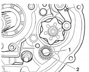
4. Release the two fixings and remove the baffle plate from the crankcase breather. Discard the fixings.
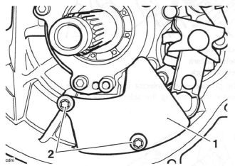
- Crankcase breather baffle plate
- Fixings
5. If not already removed, note the position and orientation of the gear pedal crank in relation to the shaft, then remove the crank.
6. Remove the E-clip and washer from the gear pedal end of the gear change shaft.
- Gear change shaft
- E-clip
- Washer
7. Withdraw the gear change shaft from the clutch end of the crankcase.
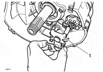
- Gear change shaft
Note:
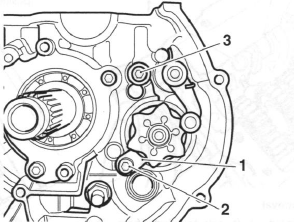
- The detent arm is held in position under spring pressure. Prior to removal, note the orientation of the detent arm, fixing and spring, relative to the selector drum detent wheel. The same orientation must be retained on assembly.
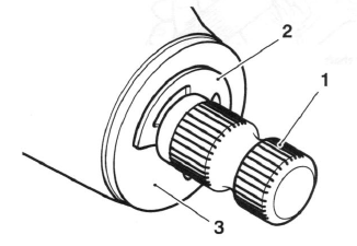
8. Remove and discard the fixing securing the detent arm.
9. Withdraw the detent arm complete with its flanged sleeve, spring and washer.
- Detent arm
- Fixing
- Spring
- Detent wheel
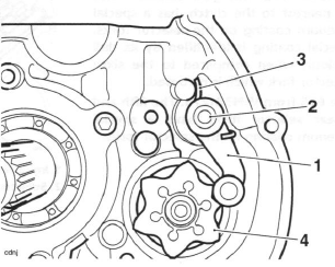
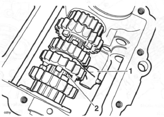
10. Remove and discard the two selector shaft retaining fixings, noting the position of the washer and the selector drum keeper plate.
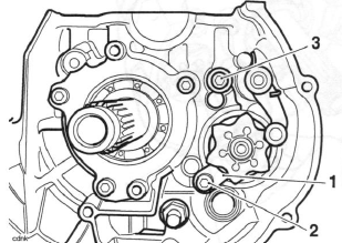
- Selector drum keeper plate
- Input selector shaft fixing
- Output selector shaft fixing and washer
Caution: The two output shaft selector forks can be fitted incorrectly. Ensure the position and orientation of the selector forks are marked prior to removal. Incorrect fitting of the selector forks will cause gearbox damage.
Note:
- All models except the Daytona 675 from VIN 381275: The fifth
gear selector fork, located nearest to the clutch, has a special molybdenum
coating on the selector forks.
This special coating is identified by its dull grey colour, when compared to the sixth gear selector fork which is chromed. - Daytona 675 from VIN381275: The fifth and sixth gear selector forks have a special molybdenum coating on the selector forks.
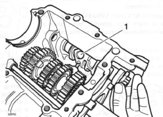
11. Slide the output selector shaft from the crankcase in the direction of the clutch. Collect the two selector forks as they are released by the selector shaft.
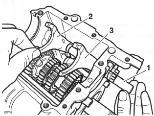
- Output selector shaft
- Sixth gear selector fork
- Fifth gear selector fork
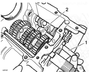
12. Noting the position of the selector fork, remove the input selector shaft, leaving the selector fork in the gearbox.
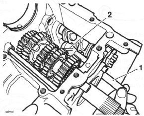
- Input selector shaft
- Selector fork
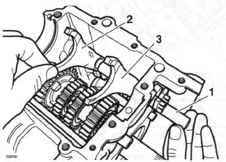
13. Withdraw the selector drum from within the crankcase.
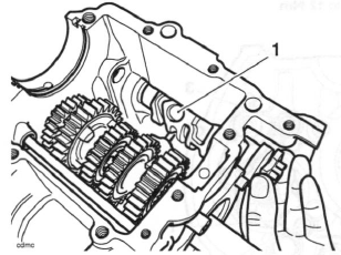
- Selector drum removal
14. Collect the input shaft selector fork from the crankcase.
Inspection
1. Examine all components for damage and/or wear, paying particular attention to the selector forks and selector drum. Replace any parts that are damaged and/or worn.
Gear selector fork thickness
Standard: 5.90 - 6.00 mm
Service limit: 5.80 mm
Gear selector groove width
Standard: 6.10 - 6.17 mm
Service limit: 6.27 mm
Selector fork to groove clearance
Service limit: 0.47 mm max
2. Examine the gear change shaft seal for damage and/ or wear. Replace the seal if damaged and/or worn.
Installation
1. Position the input shaft selector fork into the crankcase, locating the forks into the selector groove on the input shaft. Ensure the fork is fitted in the position noted during removal.
- Input shaft selector fork
- Input shaft
2. Using clean engine oil, lubricate the selector drum bearings. Lubricate the selector drum tracks with a 50/50 solution of engine oil and molybdenum disulphide grease.
3. Position the selector drum into the crankcase.
- Selector drum
4. Rotate the selector drum and ensure a smooth movement. Rectify as necessary.
Caution: The selector forks can be fitted incorrectly. Ensure the position and orientation of the selector forks are the same as noted during removal. Incorrect fitting of the selector forks will cause gearbox damage.
5. Push the input selector shaft into the crankcase from the clutch end. As the shaft is inserted locate the selector fork onto the shaft. Ensure the fork is fitted in the position noted during removal.
- Input selector shaft
- Selector fork
Note:
- For Daytona 675 up to VIN 381274, Street Triple and Street Triple R all VINs: The fifth gear selector fork, located nearest to the clutch, has a special molybdenum coating on the selector forks. This special coating is identified by its dull grey colour, when compared to the sixth gear selector fork which is chromed.
- For Daytona 675 from VIN381275 only: The fifth and sixth gear selector forks have a special molybdenum coating on the selector forks.
6. Push the output selector shaft into the crankcase from the clutch end. As the shaft is inserted, locate the selector forks. Ensure the selector forks are fitted in the positions noted during removal.
- Output selector shaft
- Sixth gear selector fork
- Fifth gear selector fork
7. Fit two new selector shaft retaining fixings, ensuring the washer and the selector drum keeper plate are fitted in the positions noted during removal. Tighten the fixings to 12 Nm.
- Selector drum/shaft keeper plate
- Fixing
- Output selector shaft fixing and washer
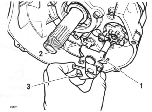
8. Assemble the detent arm as noted on removal with a new fixing and place up to the crankcase.
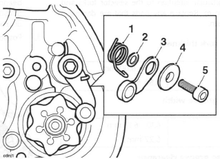
- Spring
- Washer
- Detent arm
- Flanged sleeve
- Fixing
9. Hold the detent arm assembly in position and insert a new fixing. Start the thread and push the detent arm, using finger pressure only, to locate on the selector drum detent wheel.
Ensure the detent arm remains correctly located on the detent wheel and the spring is correctly seated in the recess in the crankcase. Ensure the shoulder of the flanged sleeve is located in the bore of the detent arm and tighten the fixing to 12 Nm.
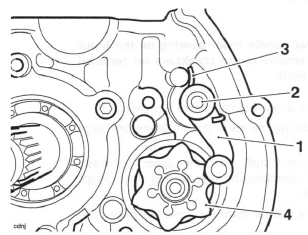
- Detent arm
- Fixing
- Spring
- Selector drum detent wheel
10. Rotate the selector drum to the neutral position.
Ensure that the detent arm locates in the raised profile in the detent wheel (neutral position).
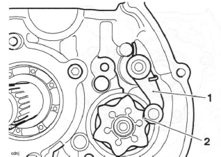
- Detent arm
- Neutral position
11. Using clean engine oil, lubricate the lip of the seal on the gear change shaft.
- Gear change shaft seal
- Gear change shaft bearing
12. Lubricate, with a 50/50 solution of engine oil and molybdenum disulphide grease, both sides of the forks and the slider plates of the selector mechanism on the gear change shaft.
Caution: Take care to avoid damaging the lip of the seal when inserting the gear change shaft into the crankcase. A damaged seal will lead to oil loss and could result in engine damage.
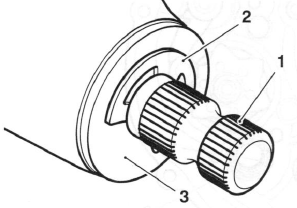
13. Insert the gear change shaft into the crankcase.
Gently push the gear pedal end of the shaft through the bearing and lip seal at the clutch side of the crankcase, and the sealed bearing, located at the gear pedal side of the crankcase.
- Gearchange shaft
- Abutment bolt
- Spring
14. Ensure that the gear change shaft fingers locate in the detent wheel/arm and that the spring fits either side of the abutment bolt.
15. Fit the washer and E-clip to the gear pedal end of the gear change shaft.
- Gear change shaft
- E-clip
- Washer
16. Fit the gear pedal crank to the shaft in the same orientation as noted prior to removal. Ensure the 'dot' mark on the shaft aligns with the split line on the gear pedal crank. Tighten the fixing to 9 Nm.
17. Incorporating new fixings, refit the baffle plate to the crankcase breather. Tighten the fixings to 9 Nm.
18. Refit the output shaft.
19. Assemble the two halves of the crankcase.
20. Refit the engine to the frame.
See also:
 Triumph Street Triple S - Service manual > Transmission
Exploded View, Input and Output Shafts - up to Engine Number 330118
Triumph Street Triple S - Service manual > Input and Output Shafts Assemblies
Removal Note: The input and output shafts may be removed from the upper crankcase after first separating the lower crankcase from the upper.
 Benelli Imperiale 400
 BMW F900XR
 Honda CB500X
 KTM 390 Adventure
 Triumph Street Triple S
 Yamaha MT-03
 Kawasaki Z400
 Triumph Street Triple S
 Yamaha MT-03