 Yamaha MT-03 - Service manual > Rear brake
Introduction
WARNING
Disc brake components rarely require disassembly.
Therefore, always follow these preventive measures:
- Never disassemble brake components unless absolutely necessary.
- If any connection on the hydraulic brake system is disconnected, the entire brake system must be disassembled, drained, cleaned, properly filled, and bled after reassembly.
- Never use solvents on internal brake components.
- Use only clean or new brake fluid for cleaning brake components.
- Brake fluid may damage painted surfaces and plastic parts. Therefore, always clean up any spilt brake fluid immediately.
- Avoid brake fluid coming into contact with the eyes as it can cause serious injury.
- FIRST AID FOR BRAKE FLUID ENTERING THE EYES:
- Flush with water for 15 minutes and get immediate.
Checking the rear brake disc
1. Remove:
- Rear wheel
2. Check:
- Brake disc
Damage/galling → Replace.
3. Measure:
- Brake disc deflection
Out of specification → Correct the brake disc deflection or replace the brake disc.
 Brake disc deflection limit
0.15 mm (0.0059 in)
Brake disc deflection limit
0.15 mm (0.0059 in)
4. Measure:
- Brake disc thickness
Measure the brake disc thickness at a few different locations.
Out of specification → Replace.
 Brake disc thickness limit
4.5 mm (0.18 in)
Brake disc thickness limit
4.5 mm (0.18 in)
5. Adjust:
- Brake disc deflection
 Rear brake disc bolt
30 Nm (3.0 m*kg, 22 ft*lb)
LOCTITE
Rear brake disc bolt
30 Nm (3.0 m*kg, 22 ft*lb)
LOCTITE
6. Install:
- Rear wheel
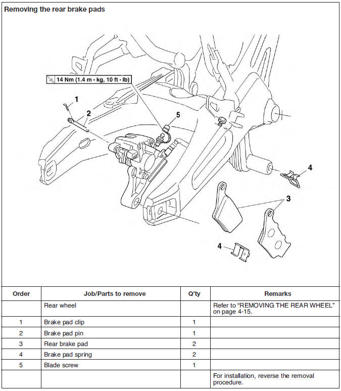
Replacing the rear brake pads
NOTE:
When replacing the brake pads, it is not necessary to disconnect the brake hose or disassemble the brake caliper.
1. Measure:
- Brake pad wear limit "a"
Out of specification → Replace the brake pads as a set.
 Brake pad lining thickness
(inner)
Brake pad lining thickness
(inner)
4.7 mm (0.18 in)
Limit
1.0 mm (0.04 in)
Brake pad lining thickness (outer)
4.7 mm (0.18 in)
Limit 1.0 mm (0.04 in)
2. Install:
- Brake pad springs
- Brake pads
NOTE:
Always install new brake pads and brake pad springs as a set.
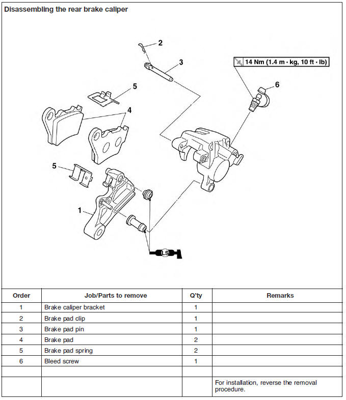
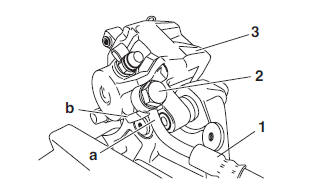
a. Connect a clear plastic hose "1" tightly to the bleed screw "2". Put the other end of the hose into an open container.
b. Loosen the bleed screw and push the brake caliper piston into the brake caliper with your finger
c. Tighten the bleed screw
 Bleed screw (rear brake
caliper)
14 Nm (1.4 m*kg, 10 ft*lb)
Bleed screw (rear brake
caliper)
14 Nm (1.4 m*kg, 10 ft*lb)
d. Install new brake pads and new brake pad springs.
3. Install:
- Brake pad pin
- Brake pad clip
- Brake caliper
- Rear wheel
4. Check:
- Brake fluid level
Below the minimum level mark "a" → Add the recommended brake fluid to the proper level.
5. Check:
- Brake pedal operation
Soft or spongy feeling → Bleed the brake system.
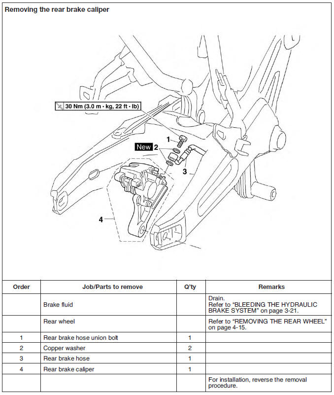
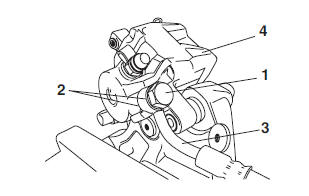
Removing the rear brake caliper
NOTE:
Before disassembling the brake caliper, drain the brake fluid from the entire brake system.
1. Remove:
- Rear wheel
- Rear brake hose union bolt "1"
- Copper washers "2"
- Rear brake hose "3"
- Rear brake caliper "4"
NOTE:
Put the end of the brake hose into a container and pump out the brake fluid carefully.
Disassembling the rear brake caliper
1. Remove:
- Brake caliper piston "1"
a. Blow compressed air into the brake hose joint opening "a" to force out the pistons from the brake caliper.
WARNING
- Cover the brake caliper piston with a rag.
Be careful not to get injured when the piston is expelled from the brake caliper.
- Never try to pry out the brake caliper piston.
b. Remove the brake caliper piston seals.
Checking the rear brake caliper
1. Check:
- Brake caliper piston
Rust/scratches/wear → Replace the brake caliper assembly.
- Brake caliper cylinder
Scratches/wear → Replace the brake caliper assembly.
- Brake caliper body
Cracks/damage → Replace the brake caliper assembly.
- Brake fluid delivery passages (brake caliper body)
Obstruction → Blow out with compressed air.
WARNING
Whenever a brake caliper is disassembled, replace the brake caliper piston seals.
2. Check:
- Brake caliper bracket "1"
Cracks/damage → Replace.
Assembling the rear brake caliper
WARNING
- Before installation, all internal brake components should be cleaned and lubricated with clean or new brake fluid.
- Never use solvents on internal brake components as they will cause the piston seals to swell and distort.
- Whenever a brake caliper is disassembled, replace the brake caliper piston seals.
 Recommended fluid
DOT 4
Recommended fluid
DOT 4
Installing the rear brake caliper
1. Install:
- Brake caliper springs
- Brake pads
- Brake pad pin
- Brake pad clip
- Brake caliper
- Rear wheel
- Copper washers

- Rear brake hose "1"
- Rear brake hose union bolt "2"
 Rear brake hose union bolt
30 Nm (3.0 m*kg, 22 ft*lb)
Rear brake hose union bolt
30 Nm (3.0 m*kg, 22 ft*lb)
WARNING
Proper brake hose routing is essential to insure safe vehicle operation.
CAUTION:
When installing the brake hose onto the brake caliper "3", make sure the brake pipe "a" touches the projection "b" on the brake caliper.
2. Fill:
- Brake fluid reservoir (with the specified amount of the recommended brake fluid)
 Recommended fluid
DOT 4
Recommended fluid
DOT 4
WARNING
- Use only the designated brake fluid. Other brake fluids may cause the rubber seals to deteriorate, causing leakage and poor brake performance.
- Refill with the same type of brake fluid that is already in the system. Mixing brake fluids may result in a harmful chemical reaction, leading to poor brake performance.
- When refilling, be careful that water does not enter the brake fluid reservoir. Water will significantly lower the boiling point of the brake fluid and could cause vapor lock.
CAUTION:
Brake fluid may damage painted surfaces and plastic parts. Therefore, always clean up any spilt brake fluid immediately.
3. Bleed:
- Brake system
4. Check:
- Brake fluid level
Below the minimum level mark "a" → Add the recommended brake fluid to the proper level.
5. Check:
- Brake pedal operation
Soft or spongy feeling → Bleed the brake system.
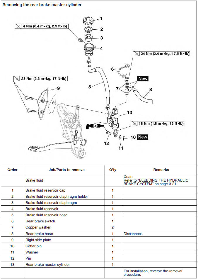
Removing the rear brake master cylinder
NOTE:
Before removing the rear brake master cylinder, drain the brake fluid from the entire brake system.
1. Remove:
- Rear brake switch "1"
- Copper washers "2"
- Rear brake hose "3"
NOTE:
To collect any remaining brake fluid, place a container under the master cylinder and the end of the brake hose.
Checking the rear brake master cylinder
1. Check:
- Brake master cylinder.
Damage/scratches/wear → Replace.
- Brake fluid delivery passages (brake master cylinder body) Obstruction → Blow out with compressed air.
2. Check:
- Brake master cylinder kit
- Damage/scratches/wear → Replace.
3. Check:
- Brake fluid reservoir.
Cracks/damage → Replace.
- Brake fluid reservoir diaphragm.
Cracks/damage → Replace.
4. Check:
Brake hoses.
Cracks/damage/wear → Replace.
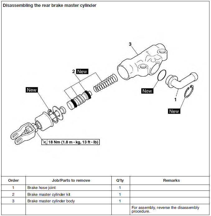
Assembling the rear brake master cylinder
WARNING
- Before installation, all internal brake components should be cleaned and lubricated with clean or new brake fluid.
- Never use solvents on internal brake components.
- Whenever a master cylinder is disassembled, replace the piston seals and dust seals.
 Recommended fluid
DOT 4
Recommended fluid
DOT 4
1. Install:
- Brake master cylinder kit
- Joint "1"
NOTE:
Turn the adjusting bolt "2" until the clearance "a" is within the specified limits when install the joint "1".
 Clearance
2.1 mm (0.08 in)
Clearance
2.1 mm (0.08 in)
2. Tighten:
- Nut "3"
 Brake master cylinder
adjusting
nut
18 Nm (1.8 m*kg, 13 ft*lb)
Brake master cylinder
adjusting
nut
18 Nm (1.8 m*kg, 13 ft*lb)
Installing the rear brake master cylinder
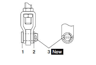
1. Install:
- Brake master cylinder
- Pin "1"
- Washer "2"
- Cotter pin "3"

NOTE:
Install the cotter pin and bend the ends as shown.
2. Install:
- Right side plate
 Right side plate bolt
23 Nm (2.3 m*kg, 17 ft*lb)
Right side plate bolt
23 Nm (2.3 m*kg, 17 ft*lb)
- Copper washers "2"
- Rear brake hose "3"
- Rear brake switch "1"
 Rear brake switch
24 Nm (2.4 m*kg, 17.5 ft*lb)
Rear brake switch
24 Nm (2.4 m*kg, 17.5 ft*lb)
WARNING
Proper brake hose routing is essential to insure safe vehicle operation.
CAUTION:
When installing the brake hose onto the brake master cylinder, make sure the brake pipe touches the projection "a" as shown.
3. Fill:
- Brake fluid reservoir (with the specified amount of the recommended brake fluid)
 Recommended fluid
DOT 4
Recommended fluid
DOT 4
WARNING
- Use only the designated brake fluid. Other brake fluids may cause the rubber seals to deteriorate, causing leakage and poor brake performance.
- Refill with the same type of brake fluid that is already in the system. Mixing brake fluids may result in a harmful chemical reaction, leading to poor brake performance.
- When refilling, be careful that water does not enter the brake fluid reservoir. Water will significantly lower the boiling point of the brake fluid and could cause vapor lock.
CAUTION:
Brake fluid may damage painted surfaces and plastic parts. Therefore, always clean up any spilt brake fluid immediately.
4. Bleed:
- Brake system
5. Check:
- Brake fluid level
Below the minimum level mark "a" → Add the recommended brake fluid to the proper level.
6. Check:
- Brake pedal operation
Soft or spongy feeling → Bleed the brake system.
7. Adjust:
- Brake pedal position
Handlebar
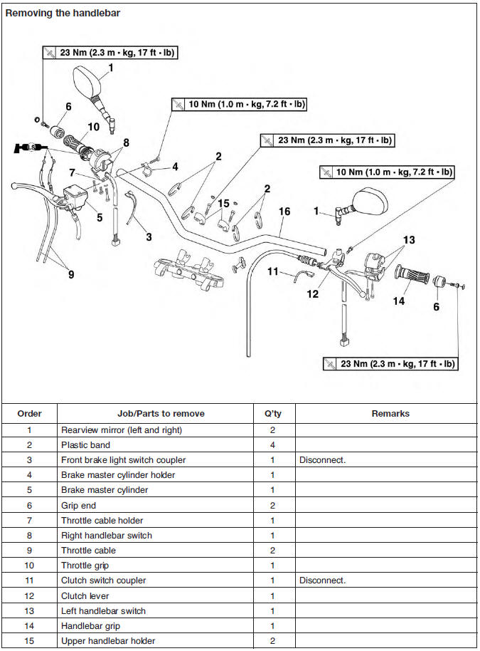
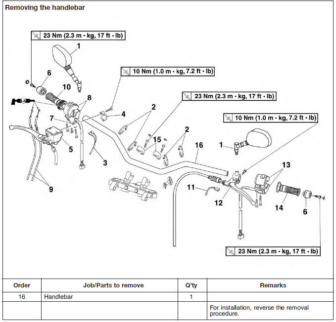
Removing the handlebar
1. Stand the vehicle on a level surface.
WARNING
Securely support the vehicle so that there is no danger of it falling over.
2. Remove:
- Handlebar grip "1"
NOTE:
Blow compressed air between the handlebar and the left handlebar grip, and gradually push the grip off the handlebar
Checking the handlebar
1. Check:
- Handlebar
Bends/cracks/damage → Replace.
WARNING
Do not attempt to straighten a bent handlebar as this may dangerously weaken it.
Installing the handlebar
1. Stand the vehicle on a level surface.
WARNING
Securely support the vehicle so that there is no danger of it falling over.
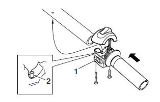
2. Install:
- Throttle grip "1" (on the handlebar)
NOTE:
Align the projection "2" on the handlebar switch with the hole in the handlebar.
 Handlebar switch bolt
2 Nm (0.2 m*kg, 1.4 ft*lb)
Handlebar switch bolt
2 Nm (0.2 m*kg, 1.4 ft*lb)
NOTE:
Check the throttle grip for smooth action.
WARNING
Proper cable routing is essential to assure safe motorcycle operation.
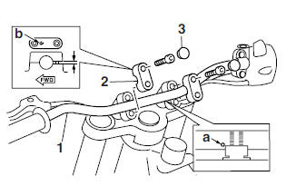
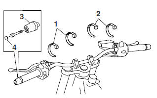
3. Install:
- Handlebar "1"
- Upper handlebar holders "2"
- Bolt caps "3"
NOTE:
- Align the punch mark "a" on the handlebar with the top of the lower handlebar holder.
- Install the handlebar holders with the arrow "b" mark facing forward.
 Upper handlebar holder bolt
23 Nm (2.3 m*kg, 17 ft*lb)
Upper handlebar holder bolt
23 Nm (2.3 m*kg, 17 ft*lb)
CAUTION:
First tighten the bolts on the front side, and then tighten the bolts on the rear side.
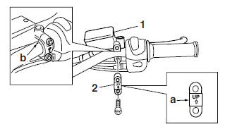
4. Install:
- Front brake master cylinder "1"
- Front brake master cylinder holder "2"
NOTE:
- Make sure that the "UP" mark "a" with the bracket is pointed upward.
- Align the punch mark "b" on the handlebar with the gap of the master cylinder bracket.
 Front brake master cylinder
holder bolt
10 Nm (1.0 m*kg, 7.2 ft*lb)
Front brake master cylinder
holder bolt
10 Nm (1.0 m*kg, 7.2 ft*lb)
NOTE:
- Tighten the bolts in stages and maintain an equal gap on each side of the bracket to specification.
- Check the brake lever for smooth action.
WARNING
Proper cable routing is essential to assure safe motorcycle operation.
5. Install:
- Left handlebar switch "1"
NOTE:
Align the projection "a" on the left handlebar switch with the hole in the handlebar.
 Handlebar switch bolt
2 Nm (0.2 m*kg, 1.4 ft*lb)
Handlebar switch bolt
2 Nm (0.2 m*kg, 1.4 ft*lb)
WARNING
Proper cable routing is essential to assure safe motorcycle operation.
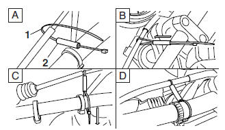
6. Install:
- Clutch cable "1"
- Cable boot "2"
NOTE:
- Lubricate the pivoting part "a" of the clutch lever.
- Turn in the adjuster "b" on the lever holder until tight. Next, align the slit in the adjuster and cable socket with the slit in the lever holder.
- Insert the cable end into the lever hole. Next, while pulling the outer cable in the direction opposite to the lever, seat the outer cable into the cable socket.
7. Connect:
- Clutch lever switch "3"
WARNING
Check the clutch lever for smooth action.
8. Install:
- Handlebar grip "1"
a. Apply a thin coat of rubber adhesive onto the left end of the handlebar.
b. Slide the handlebar grip over the left end of the handlebar.
c. Wipe off any excess rubber adhesive with a clean rag.
WARNING
Do not touch the handlebar grip until the rubber adhesive has fully dried.
NOTE:
There should be 1-3 mm (0.04-0.12 in) of clearance "a" between the handlebar grip and the grip end.
9. Install:
- Cable ties "1" (secure the left handlebar switch lead)
- Cable ties "2" (secure the right handlebar switch lead)
- Grip ends "3"
- Bolt caps "4"
 Grip end bolt
23 Nm (2.3 m*kg, 17 ft*lb)
Grip end bolt
23 Nm (2.3 m*kg, 17 ft*lb)
NOTE:
Refer to "CABLE ROUTING"
10. Install:
- Band "1" (secure the clutch cable)
- Piece connecting "2"
11. Install:
- Left rear view mirror "1"
- Right rear view mirror "2"

 Benelli Imperiale 400
 BMW F900XR
 Honda CB500X
 KTM 390 Adventure
 Triumph Street Triple S
 Yamaha MT-03
 Kawasaki Z400
 Triumph Street Triple S
 Yamaha MT-03