 Yamaha MT-03 - Service manual > Features
Outline of the FI system
The main function of a fuel supply system is to provide fuel to the combustion chamber at the optimum air-fuel ratio in accordance with the engine operating conditions and the atmospheric temperature.
In a conventional carburetor system, the air-fuel ratio of the mixture that is supplied to the combustion chamber is created by the volume of the intake air and the fuel that is metered by the jet used in the respective chamber. Despite the same volume of intake air, the fuel volume requirement varies with the engine operating conditions, such as acceleration, deceleration, or operation under a heavy load. Carburetors that meter the fuel through the use of jets have been provided with various auxiliary devices, so that an optimum air-fuel ratio can be achieved to accommodate the constant changes in the operating conditions of the engine. As the requirements for engines to deliver more performance and cleaner exhaust gases increase, it becomes necessary to control the air-fuel ratio in a more precise and finely tuned manner. To accommodate this need, this model has adopted an electronically controlled fuel injection (FI) system in place of a conventional carburetor system. This system can achieve an optimum air-fuel ratio required by the engine at all times by using a microprocessor that regulates the fuel injection volume according to the engine operating conditions detected by various sensors. Adoption of the FI system has resulted in a highly precise fuel supply, improved engine response, better fuel economy, and reduced exhaust emissions. Furthermore, the air induction system (AI system) has been placed under computer control together with the FI system in order to realize cleaner exhaust gases.
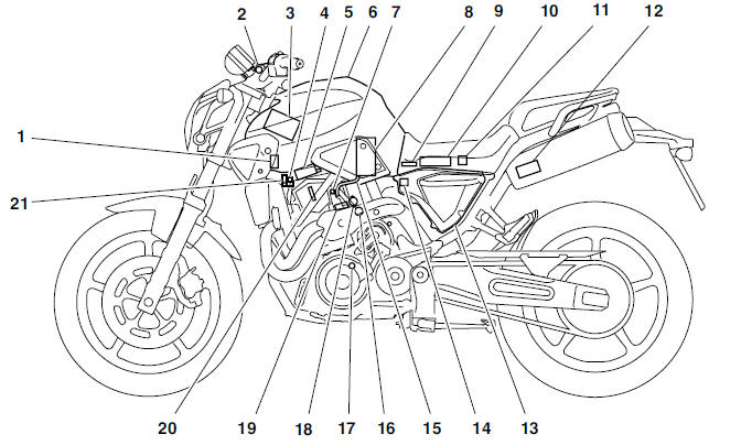
- Fuel injection system relay
- Engine trouble warning light
- Battery
- Air induction system solenoid
- Ignition coil/Spark plug
- Fuel tank
- Idling adjustment screw
- Fuel pump
- Intake air pressure sensor
- ECU
- Lean angle cut-off switch
- Catalytic converter
- Air filter case
- Intake air temperature sensor
- Fuel hose
- Coolant temperature sensor
- Crankshaft position sensor
- Throttle position sensor
- Fuel injector
- Spark plug
- Air cut-off valve
FI system
The fuel pump delivers fuel to the injector via the fuel filter. The pressure regulator maintains the fuel pressure that is applied to the injector at 324 kPa (3.24 kg/cm2, 46.1 psi) higher than the intake manifold pressure. Accordingly, when the energizing signal from the ECU energizes the injector, the fuel passage opens, causing the fuel to be injected into the intake manifold only during the time the passage remains open. Therefore, the longer the length of time the injector is energized (injection duration), the greater the volume of fuel that is supplied. Conversely, the shorter the length of time the injector is energized (injection duration), the lesser the volume of fuel that is supplied.
The injection duration and the injection timing are controlled by the ECU. Signals that are input from the throttle position sensor, crankshaft position sensor, intake air pressure sensor, intake air temperature sensor, and coolant temperature sensor enable the ECU to determine the injection duration.
The injection timing is determined through the signal from the crankshaft position sensor. As a result, the volume of fuel that is required by the engine can be supplied at all times in accordance with the driving conditions.
Illustration is for reference only
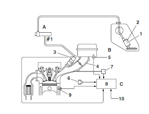
- Fuel pump
- Pressure regulator
- Fuel injector
- Throttle body
- Intake air temperature sensor
- Throttle position sensor
- Intake air pressure sensor
- ECU
- Coolant temperature sensor
- Crankshaft position sensor
- Fuel system
- Air system
- Control system
Instrument functions
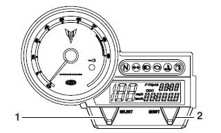
Multi-function meter unit
WARNING
Be sure to stop the vehicle before making any setting changes to the multi-function meter unit.
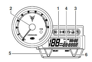
- Speedometer
- Tachometer
- Clock
- Odometer/Tripmeters/Fuel reserve tripmeter
- "SELECT" button
- "RESET" button
- The multi-function meter unit is equipped with the following:
- a speedometer (which shows the riding speed)
- a tachometer (which shows engine speed)
- an odometer (which shows the total distance traveled)
- two tripmeters (which show the distance traveled since they were last set to zero)
- a fuel reserve tripmeter (which shows the distance traveled since the fuel level warning light came on)
- a clock
- a self-diagnosis device
- an indicator lights brightness control mode.
To switch the speedometer and odometer/tripmeter displays between kilometers and miles, push the "SELECT" and "RESET" buttons together and turn the key to "ON". When the digits start flashing on the display, push the "SELECT" button to choose kilometers or miles.
NOTE:
Be sure to turn the key to "ON" before using the "SELECT" and "RESET" buttons.
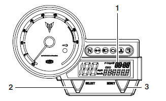
Tachometer
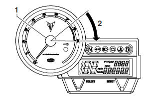
- Tachometer
- Red zone
The electric tachometer allows the rider to monitor the engine speed and keep it within the ideal power range.
CAUTION:
Do not operate the engine in the tachometer red zone. Red zone: 7500 r/min and above.
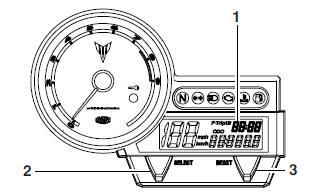
Odometer, tripmeter modes
- "SELECT" button
- "RESET" button
Pushing the "SELECT" button switches the display between the odometer mode "ODO" and the tripmeter modes "TRIP 1" and "TRIP 2" in the following order:
ODO → TRIP 1 → TRIP 2 → ODO
If the fuel level warning light comes on, the odometer display will automatically change to the fuel reserve tripmeter mode "F-TRIP" and start counting the distance traveled from that point. In that case, push the "SELECT" button to switch the display between the various tripmeter, odometer modes in the following order:
F-TRIP → ODO →TRIP 1 →TRIP 2 → F-TRIP
To reset a tripmeter, select it by pushing the "SELECT" button, and then push the "RESET" button for at least four seconds. If you do not reset the fuel reserve tripmeter manually, it will reset itself automatically and the display will return to the prior mode after refueling and traveling 5 km (3 mi).
Clock mode
- Clock
- "SELECT" button
- "RESET" button
Turn the key to "ON".
To set the clock
1. Push the "SELECT" button for at least two seconds.
2. When the hour digits start flashing, push the "RESET" button to set the hours.
3. Push the "SELECT" button, and the minute digits will start flashing.
4. Push the "RESET" button to set the minutes.
5. Push the "SELECT" button, and then release it to start the clock.
Self-diagnosis devices
- Engine trouble warning light "U"
- Immobilizer system indicator light "
 "
"
This model is equipped with a self-diagnosis device for various electrical circuits.
If any of those circuits are defective, the engine trouble warning light will start flashing.
This model is also equipped with a self-diagnosis device for the immobilizer system.
Turn the key to "ON". If any of the immobilizer system circuits are defective, the immobilizer system indicator light will flash, and it will indicate an error code. Refer to "IMMOBILIZER SYSTEM" . However, if the indicator light slowly flashes five times, and then quickly flashes two times repeatedly, this error could be caused by signal interference. If this occurs, try the following.
1. Use the code re-registering key to start the engine.
NOTE:
Make sure there are no other immobilizer keys close to the main switch, and do not keep more than one immobilizer key on the same key ring! Immobilizer system keys may cause signal interference, which may prevent the engine from starting.
2. If the engine starts, turn it off and try starting the engine with the standard keys.
3. If one or both of the standard keys do not start the engine, re-register the standard keys.
If the multifunction display indicates an error code, note the code number, and then check the vehicle.
CAUTION:
If the display indicates an error code, the vehicle should be checked as soon as possible in order to avoid engine damage.
Indicator lights brightness control mode
- Indicator lights brightness: This function allows you to adjust the brightness of the indicator lights to suit the outside lighting conditions
To adjust the brightness of the indicator lights
1. Turn the key to "ON".
2. Push the "SELECT" button to select ODO meter mode, and then push the "RESET" button for at least five seconds.
3. Release the "RESET" button, and then select the desired lighting brightness level by pushing the "RESET" button.
See also:
 Yamaha MT-03 - Service manual > General information
Identification Vehicle identification number The vehicle identification number "1" is stamped into the right side of the steering head pipe.
Yamaha MT-03 - Service manual > Important information
Preparation for removal and disassembly 1. Before removal and disassembly, remove all dirt, mud, dust and foreign material.
 Benelli Imperiale 400
 BMW F900XR
 Honda CB500X
 KTM 390 Adventure
 Triumph Street Triple S
 Yamaha MT-03
 Kawasaki Z400
 Triumph Street Triple S
 Yamaha MT-03