 Kawasaki Z400 - Service manual > Cable, Wire, and Hose Routing
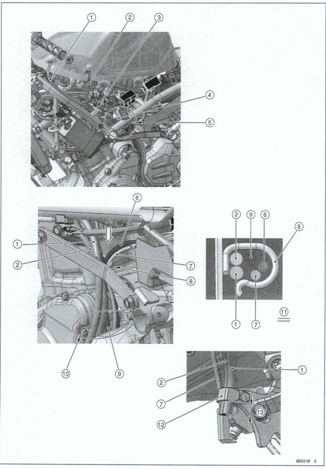
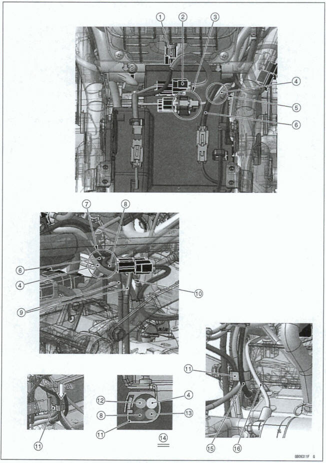
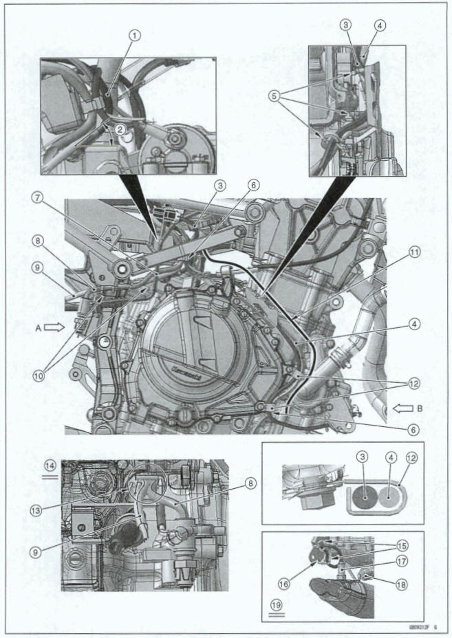
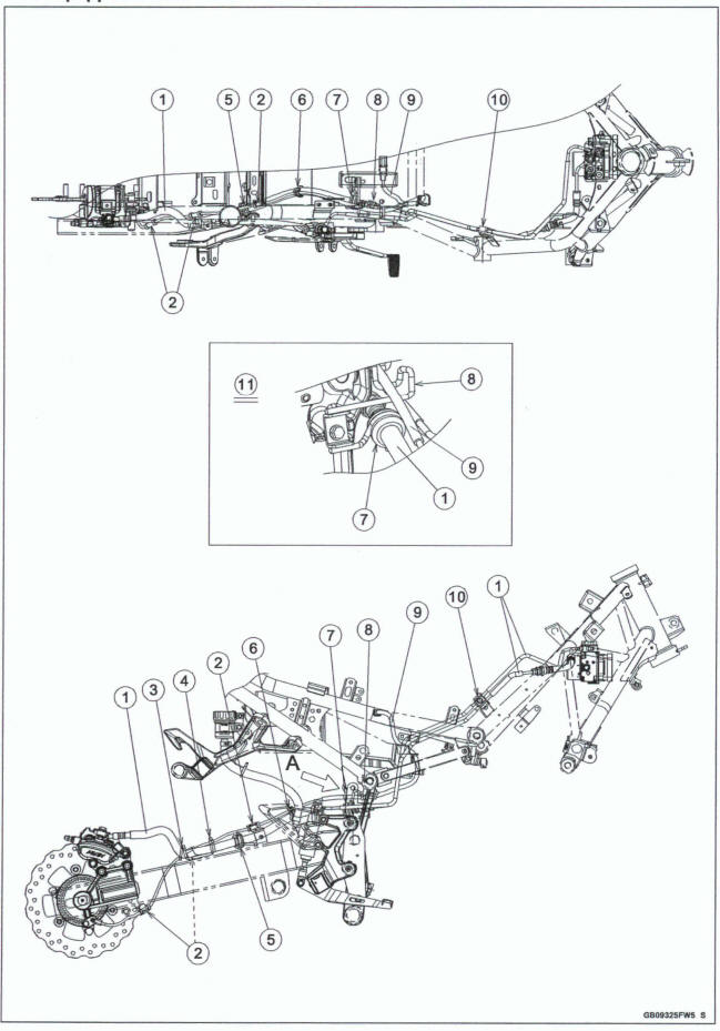
Appendix / Cable, Wire, and Hose Routing
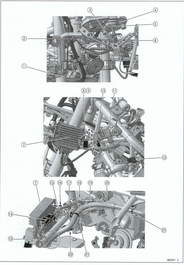
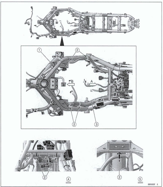
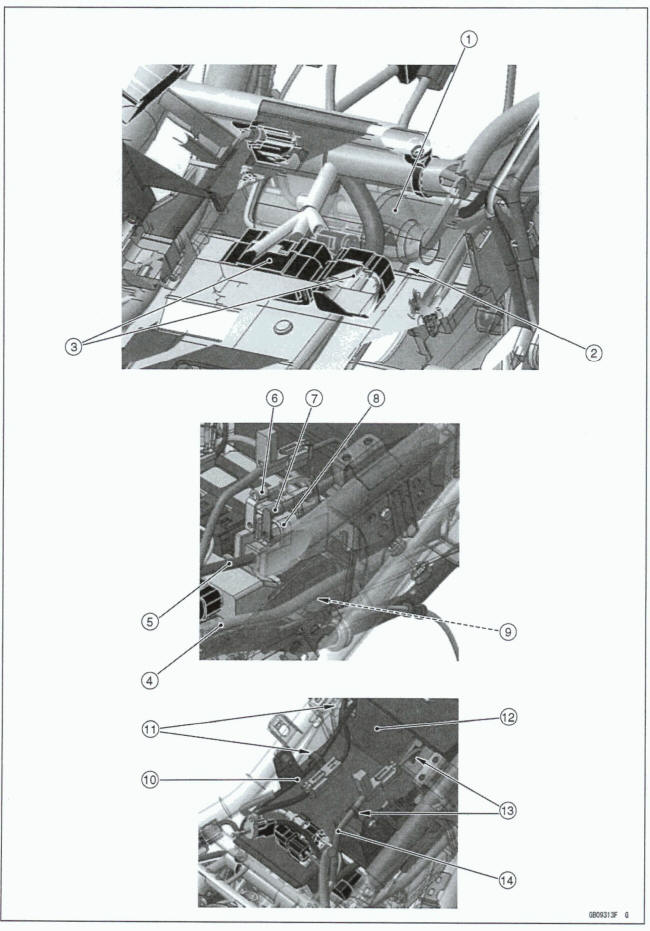
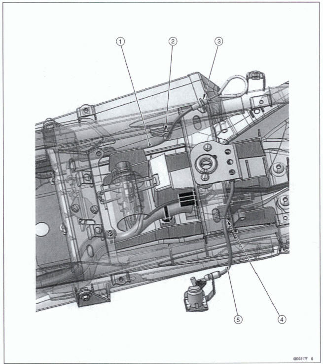
- Front Right Turn Signal Light Lead Connector (Install it to the upper fairing bracket.)
- Clamp (Hold the front right turn signal light lead.)
- Vehicle-down Sensor
- Meter
- Meter Lead Connector
- Run the meter lead through the clamp.
- Regulator/Rectifier
- Clamp (Hold the headlight lead and accessory relay lead, and make accessory relay lead connector face down.) (EX400GM)
- Clamp (Hold the headlight lead.) (EX400J)
- Accessory Relay (EX400J)
- Turn Signal Relay
- Purge Valve (Evaporative Emission Control System Equipped Models)
- Run the main harness through the clamp.
- Headlight Lead Connector (Install it to the upper fairing bracket.)
- Headlight Lead
- Accessory Connector Lead (EX400J)
- Clamp (Hold the accessory connector lead (EX400J) and headlight lead.)
- Run the headlight lead to the upside of the main harness.
- Accessory Connector
- Main Harness
- Clamps (Hold the main harness, and install it to the upper fairing bracket.)
- Front Left Turn Signal Light Lead Connector (Install it to the upper fairing bracket.)
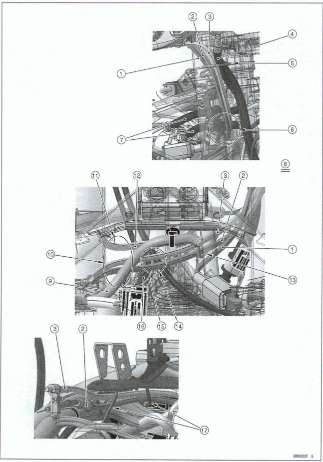
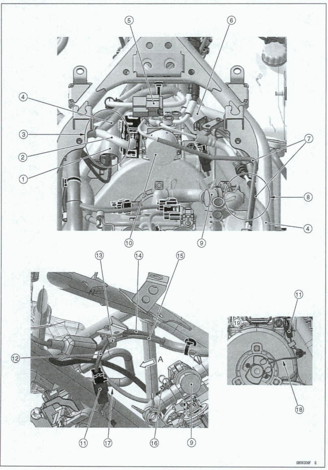
- Right Switch Housing Lead
- Throttle Cable (Decelerator)
- Throttle Cable (Accelerator)
- Front Brake Hose
- Run the front brake hose, throttle cable (accelerator), throttle cable (decelerator) and right switch housing lead through the clamp as shown.
- Run the throttle cables under the right switch housing lead and front brake hose (ABS equipped models).
- Front Brake Hoses (ABS Equipped Models)
- Viewed from Front Right Side
- Main Harness
- Run the throttle cables to the outside of the main harness.
- Run the throttle cables under the ignition switch lead.
- Ignition Switch Lead
- Front Wheel Rotation Sensor Lead (ABS Equipped Models) (Run the throttle cables to the up side of the front wheel rotation sensor lead.)
- Run the throttle cables to the upside of the horn lead and left switch housing lead.
- Horn Lead
- Left Switch Housing Lead
- Run the throttle cables through the damps.
- Clamp (Hold the horn lead, and install the clamp to the horn bracket.)
- Horn Lead
- Tilt the damp to the outside of the vehicle as shown.
- Viewed from A
- Run the horn lead between the left switch housing lead and frame pipe.
- Left Switch Housing Lead
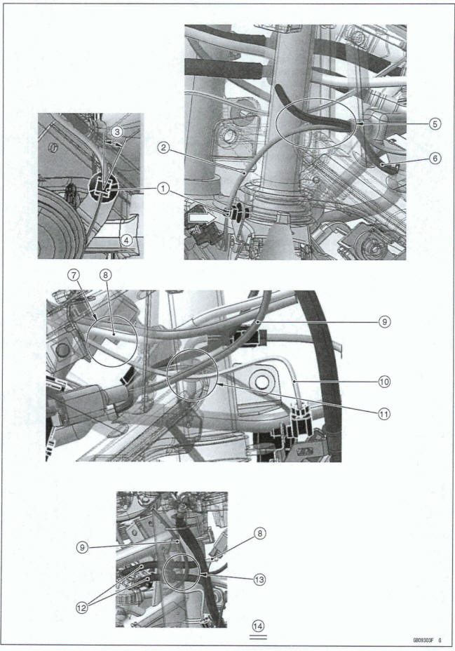
- Run the front wheel rotation sensor lead (ASS equipped models) under the ignition switch lead.
- Ignition Switch Lead
- Right Switch Housing Lead
- Front Wheel Rotation Sensor Lead (ABS Equipped Models)
- Run the front wheel rotation sensor lead (ABS equipped models) between the right switch housing Lead and frame pipe.
- Front Brake Hoses (ABS Equipped Models)
- Run the front brake hose (ABS equipped models) between the Ignition switch lead and right switch housing lead.
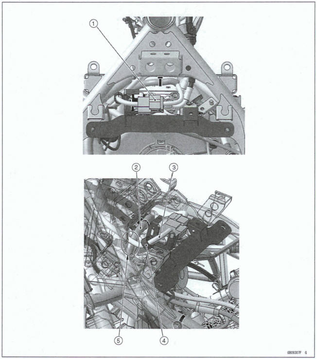
- Viewed Front Right Side
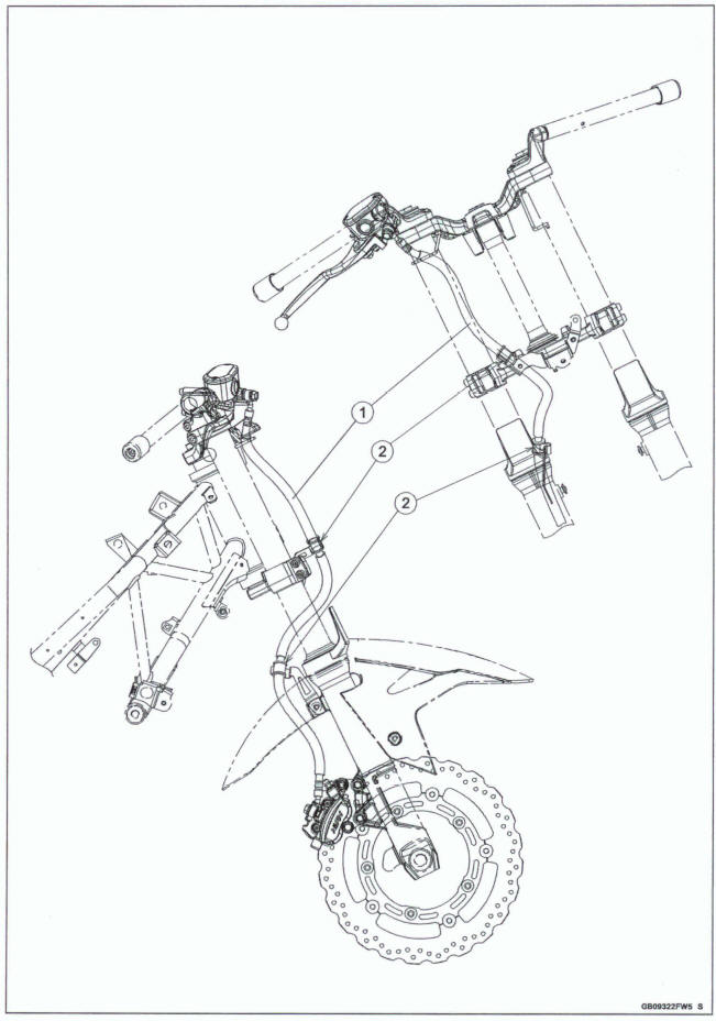
- Run the clutch cable under the right switch housing lead.
- Run the clutch cable to the inside of the frame.
- Clutch Cable
- Run the clutch cable b the outside of the frame.
- Clamp (Hold the clutch cable.)
- Clamp (Hold the clutch cable and left switch housing lead.)
- Install the damp along the joint of the clutch cable.
- Run the clutch cable to the inside of left witch housing lead.
- Left Switch Housing Lead
- Horn Lead
- Run the clutch cable between the horn lead and frame pipe.
- Run the clutch cable under the throttle cables.
- Throttle Cables
- Frame
- Clamps (Hold the main harness, and install them to the frame.)
- Main Harness
- Viewed from A
- Viewed from B
- Left Switch Housing Lead Connector
- ABS Hydraulic Unit Lead (ABS Equipped Models)
- Run the left switch housing lead connector under the main harness and ABS hydraulic unit lead (ABS equipped models).
- Main Harness
- Ignition Switch Lead Connector
- Right Switch Housing Lead Connector
- ABS Brake Pipes (ABS Equipped Models)
- Run the main harness under the ABS brake pipes (ABS equipped models).
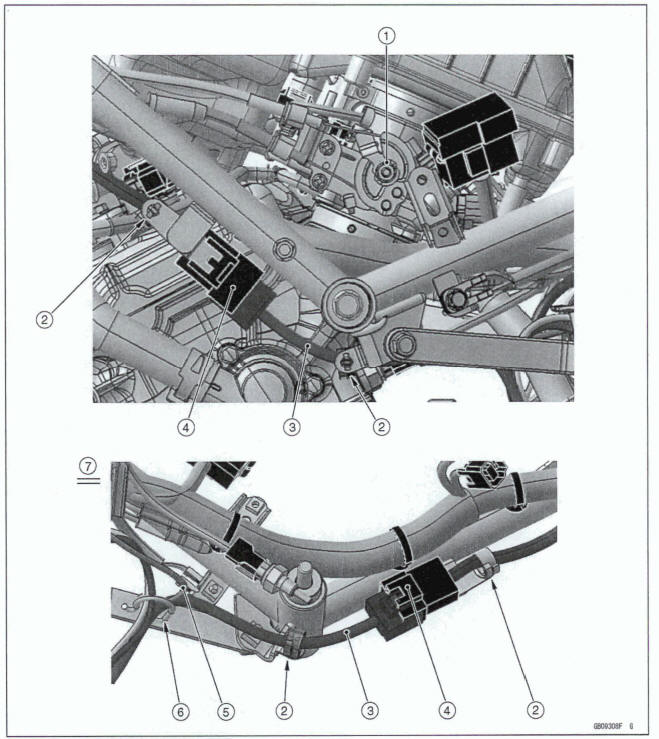
- Air Switching Valve
- ABS Hydraulic Unit (ABS Equipped Models)
- Radiator Fan Motor Lead Connector
- Radiator Fan Motor Lead
- Clamp (Hold the right switch housing lead, radiator fan motor lead and air switching valve lead.)
- Right Switch Housing Lead
- Air Switching Valve Lead
- Air Switching Valve Lead Connector
- Run the radiator fan motor lead to front side of the air switching valve lead.
- Run the radiator fan motor lead as shown.
- Viewed from A
- Ignition Switch Lead Connector (Connect it connector and install the bracket.)
- Main Harness
- Ignition Switch Lead
- Clamp (Hold the ignition switch lead.)
- Run the ignition switch lead to the upside of the main harness
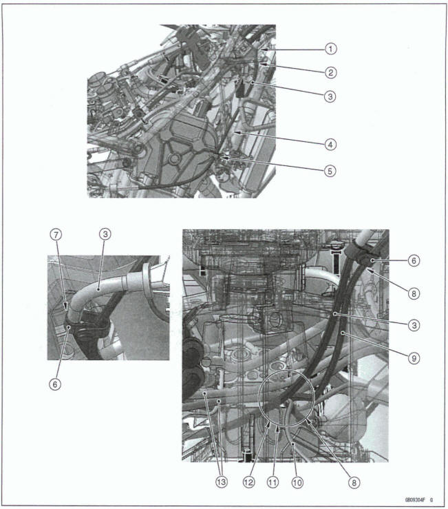
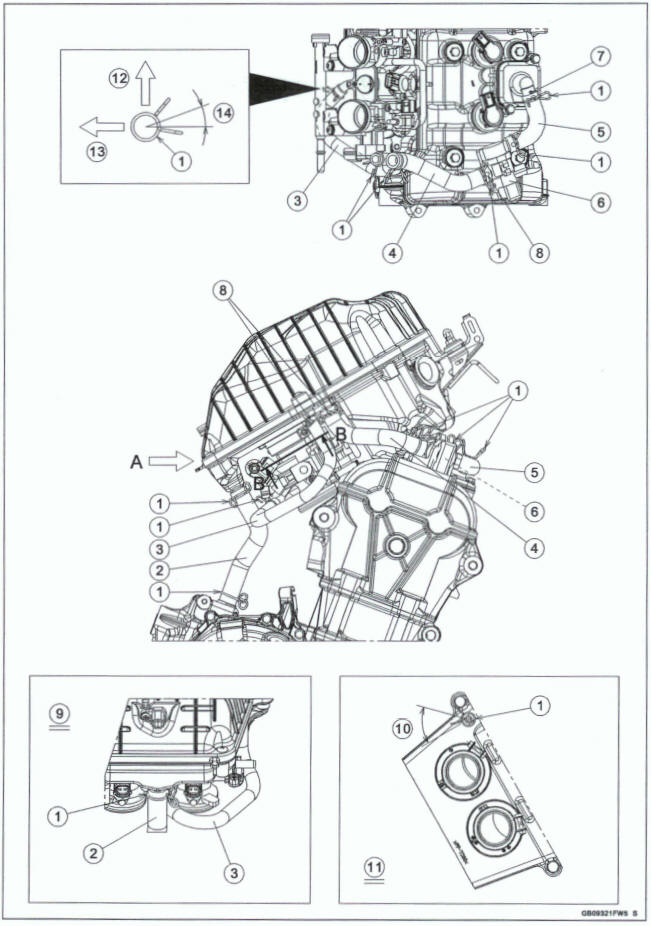
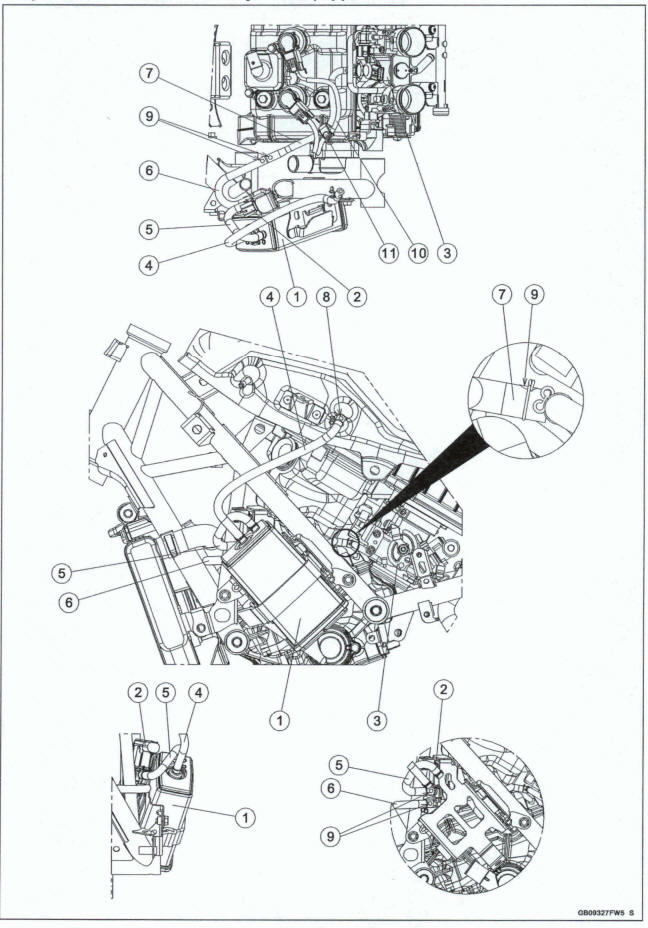
- Throttle Body Assy
- Clamps (Hold the alternator lead.)
- Alternator Lead
- Alternator Lead Connector (Install it to the bracket.)
- Crankshaft Sensor Lead
- Run the alternator lead, crankshaft sensor lad, gear position sensor lead and side stand switch lead through the clamp.
- Opposite View
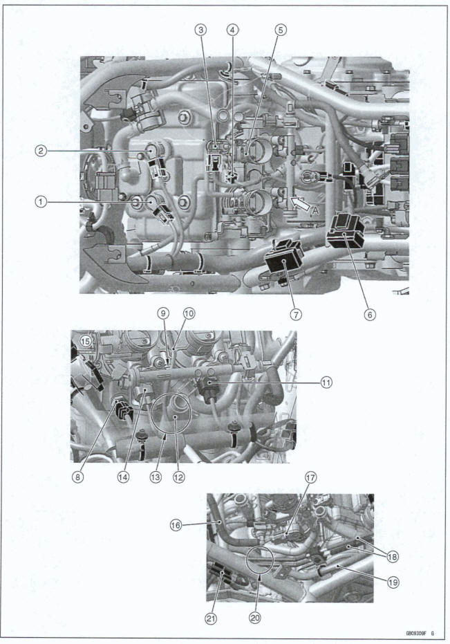
- Stick Coil #1
- stick Coil #2
- Intake Air Pressure Sensor
- Idle Speed Control Valve Actuator
- Throttle Body Assy
- Fuse Box (2)
- Fuse Box (1)
- Water Temperature Sensor
- Run the lead [lo] under the fuel pipe.
- Lead (to Intake Air Pressure Sensor and Idle Speed Control Valve Actuator)
- Fuel Injector #2
- Breather Hose
- Run the lead [10] to the left side of the breather hose.
- Fuel Injector #1
- Viewed from A
- Fuel Hose
- Main Throttle Sensor
- ABS Brake Pipes (ABS Equipped Models)
- Main Harness
- Run the main harness under the ABS brake pipes (ABS equipped models).
- Oxygen Sensor Lead Connector
- Fuel Tank Drain Hose
- Fuel Tank Breather Hose
- Clamp (Hold the fuel tank drain hose and fuel tank breather hose.)
- Main Harness
- Run the fuel tank drain hose and fuel tank breather hose between the main harness and frame.
- Gear Position Sensor Lead
- Side Stand Switch Lead
- Run the fuel tank drain hose, fuel tank breather hose, alternator lead, side stand switch lead and gear position sensor lead through the clamp.
- Alternator Lead
- Run the fuel tank drain hose, fuel tank breather hose, alternator lead, side stand switch lead and gear position sensor lead in turn from outside the vehicle as shown.
- Viewed from A
- Clamp (Hold the fuel tank drain hose, fuel tank breather hose and side stand switch lead in turn from outside the vehicle as shown.) 13.10 mm (0.39 in.)
- Intake Air Temperature Sensor Lead Connector
- Fuel Pump Lead Connector
- Rear Wheel Rotation Sensor Lead Connector (The cutout of the connector faces upward.)
- Rear Wheel Rotation Sensor Lead
- Run the rear wheel rotation sensor lead under the battery negative (-) cable.
- Battery negative (-) cable
- Run the rear wheel rotation sensor lead and battery negative (-) cable under the oxygen sensor lead.
- Oxygen Sensor Lead.
- ABS Brake Pipes (ABS Equipped Models)
- Run the ABS brake pipes( ABS equipped models) to front side of the oxygen sensor.
- Clamp (Hold the rear wheel rotation sensor lead, rear brake light switch lead, oil pressure switch lead and oxygen sensor lead)
- Rear Brake Light Switch Lead
- Oil Pressure Switch Lead
- Viewed from A
- Battery Negative (-) Cable
- Starter Motor Cable (Run the Starter motor cable to the most inside of the leads)
- Battery Negative (-) Cable
- About 30º
- Oxygen Sensor Lead
- Oil Pressure Switch Lead
- Run the oil pressure switch lead and oxygen sensor lead through the clamps.
- Align the mark of the oxygen sensor lead with the clamps.
- ABS Brake Pipes (ABS Equipped Models)
- Rear Brake Light Switch Lead
- Rear Wheel Rotation Sensor Lead
- Run the rear wheel rotation sensor lead and rear brake light switch lead to the inside of the ABS brake pipes (ABS equipped models).
- Do not twist and stretch the oxygen sensor lead and oil pressure switch lead in line area.
- Clamps (Hold the oxygen sensor lead and oil pressure switch lead. Do not touch the water pump.)
- Run the rear wheel rotation sensor lead to the inside of the rear brake light switch lead.
- Viewed from A
- Clamps (Hold the oxygen sensor lead.)
- Do not pass the oxygen sensor lead through the clamp.
- Oxygen Sensor
- Oil Pressure Switch
- Viewed from B
- Cover the gear position sensor lead connector, side stand switch lead connector and crankshaft sensor lead connector with the rubber boot.
- Run the gear position sensor lead, side stand switch lead and crankshaft sensor lead under the ECU Lead.
- ECU Lead Connectors
- Main Harness
- Starter Relay Lead
- Starter Motor Cable
- Battery Positive (+) Cable
- Starter Relay (Install it to the bracket.)
- Run the main harness under the starter relay.
- Battery Negative (-) Cable ,
- Run the battery negative (-) cable through hooks of the battery case cover.
- Battery Case Cover
- Run the battery positive (4) cable through hooks of the battery case cover (ABS equipped models).
- Battery Positive (+) Cable (ABS Equipped Models)
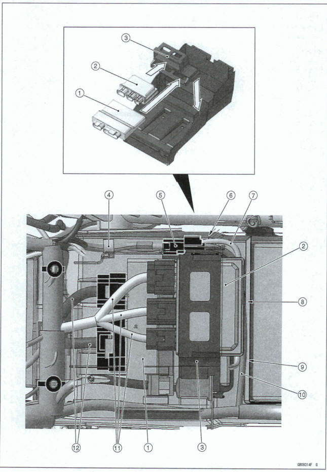
- ECU (Install it to the damper.)
- Relay Box (Install it to the damper.)
- Damper
- Clamp (Hold the rear brake light switch lead and starter motor cable.)
- Rear Brake Light Switch Lead Connector
- Run the starter motor cable under the ECU and rear brake light switch lead.
- Starter Motor Cable
- Run the rear brake light switch lead through the downside of the ECU.
- Run the rear brake light switch lead and starter motor cable through the backside of the ECU.
- Rear Brake Light Switch Lead
- Relay Box Leads
- ECU Leads
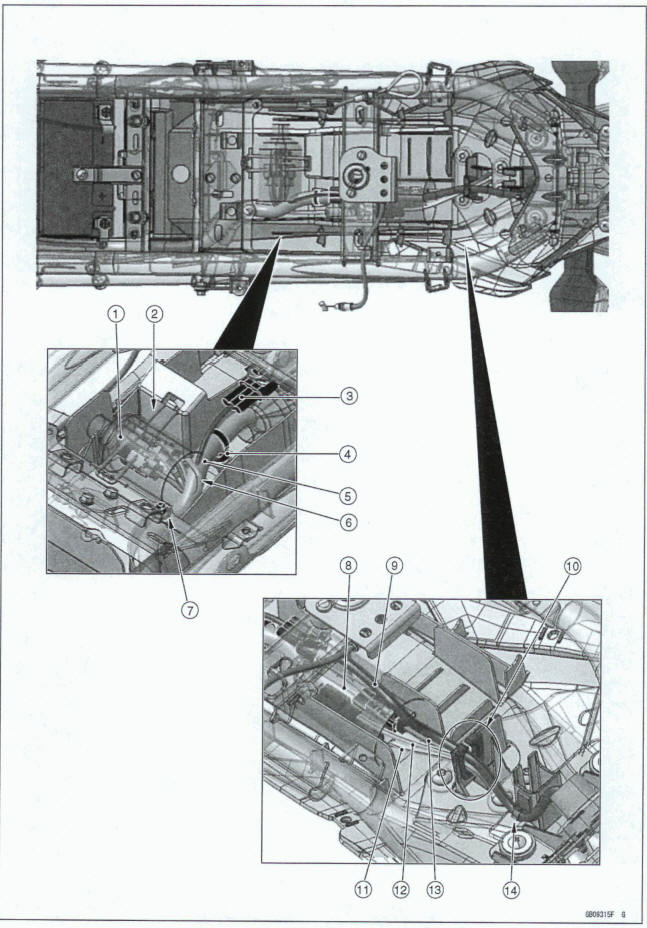
- Cover the ABS kawasaki diagnosis system connector (equipped models), ABS self-diagnosis terminal (equipped models), kawasaki diagnostic system connector and water-f joint with the rubber boot.
- Band (Hold the rubber boot.)
- Brake/Tail Light Lead Connector (Install it to the frame.)
- Clamp (Hold the main harness, and install it to the rear fender.)
- Main Harness
- Run the water-proof joint to the upside of the main harness.
- Clamp (Hold the main harness to the frame.)
- Cover the rear turn signal light lead connectors and license plate light lead connector with the rubber boot. Do not run the brake/tail light lead in the rubber boot.
- Brake/Tail Light Lead
- Run the rear turn signal light leads, license plate light lead and brake/tail light lead through the damper.
- Rear Left Turn Signal Light Lead
- License Plate Light Lead
- Rear Right Turn Signal Light Lead
- Clamp (Hold the brake/tail light lead.)
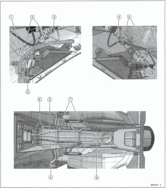
- Run the rear left turn signal light lead into the hole of the pad.
- Claps (Hold the rear left turn signal light lead)
- Rear Left Turn Signal Light Lead
- Rear Right Turn Signal Light Lead
- Clamps (Hold the rear right turn signal light lead)
- Run the rear turn signal light leads and license plate light lead underside the guide
- Run the rear turn signal light leads and license plate light lead upside the guides.
- License Plate Light Lead
- Seat Lock Cable (Front)
- Clamp (Hold the seat lock cable (front).)
- Install seat lock cable (rear) to the frame hook.
- Run the seat lock cable (mar) through the front side of the guide.
- Seat Lock Cable (Rear)
- Install the damps as shown.
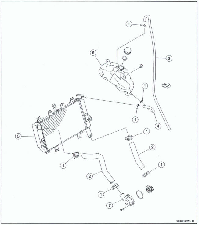
- Water Hoses
- Reserve Tank Overflow Hose
- Radiator Overflow Hose
- Radiator
- Coolant Reserve Tank
- Thermostat Cover
- Radiator
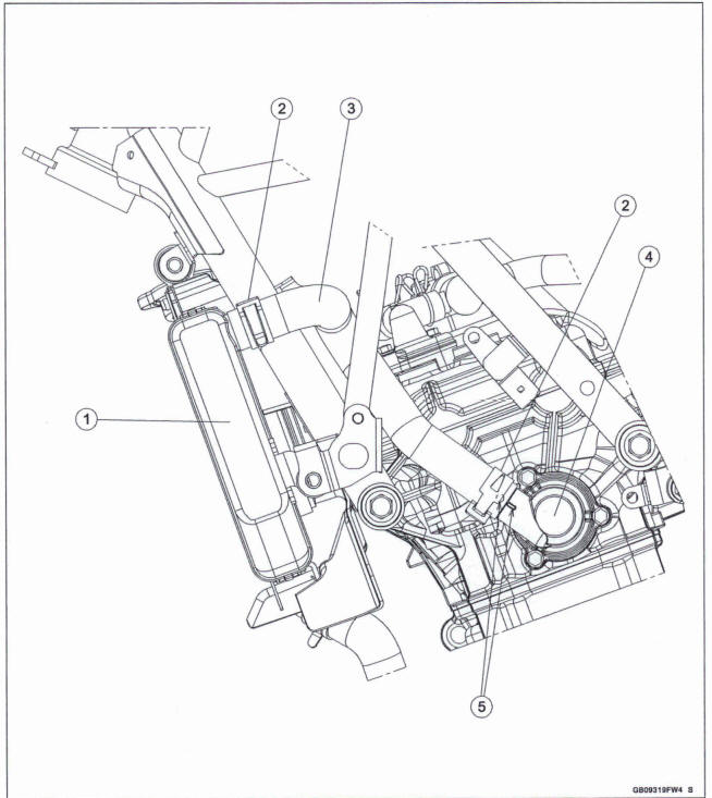
- Install the damps as shown.
- Water Hose
- Thermostat Cover
- Align the white paint mark of the water hose with the projection on the thermostat cover.
- Radiator Overflow Hose
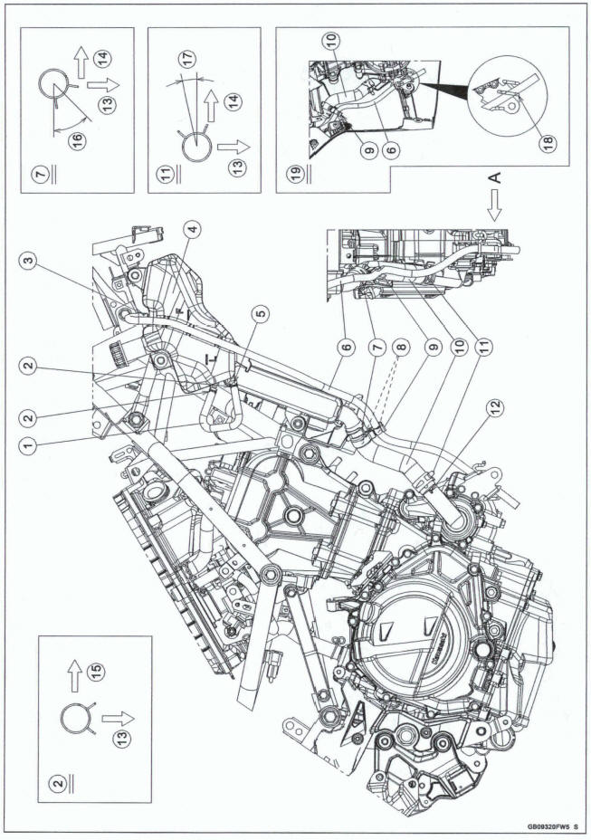
- Clamps (Hold the radiator overflow ham.)
- Clamp (Hold the reserve tank overflow hose.)
- Coolant Reserve Tank
- Install the radiator overflow hose so that the white paint mark faces right of vehicle.
- Reserve Tank Overflow Hose
- Install the clamp as shown.
- White Paint Marks
- Clamp (Hold the reserve tank overflow hose and water hose at the white painted marks d the their.)
- Water Hose
- Install the clamp as shown. '
- Align the white paint mark of fie water hose with the projection on the water pump cover.
- Right Side of Vehicle
- Front Side of Vehicle
- Upper Side of Vehicle
- 45º
- 10º
- Run the reserve tank overflow hose through the damp.
- Viewed from A
- Install the damps as shown.
- Crankcase Breather Hose
- Air Intake Hose (to Throttle Body Assy)
- Air Switching Valve Hose (to Air Cleaner Housing)
- Air Switching Valve Hose (to Air Switching Valve)
- Air Switching Valve
- Align the white paint mark of the air switching valve [5] with the mark on the fitting.
- White Paint Marks
- Viewed from A
- About 45º
- Section B-B
- Left Side of Vehicle
- Lower Side of Vehicle
- About 20º
- Front Brake Hose
- Clamps (Hold the front brake hose.)
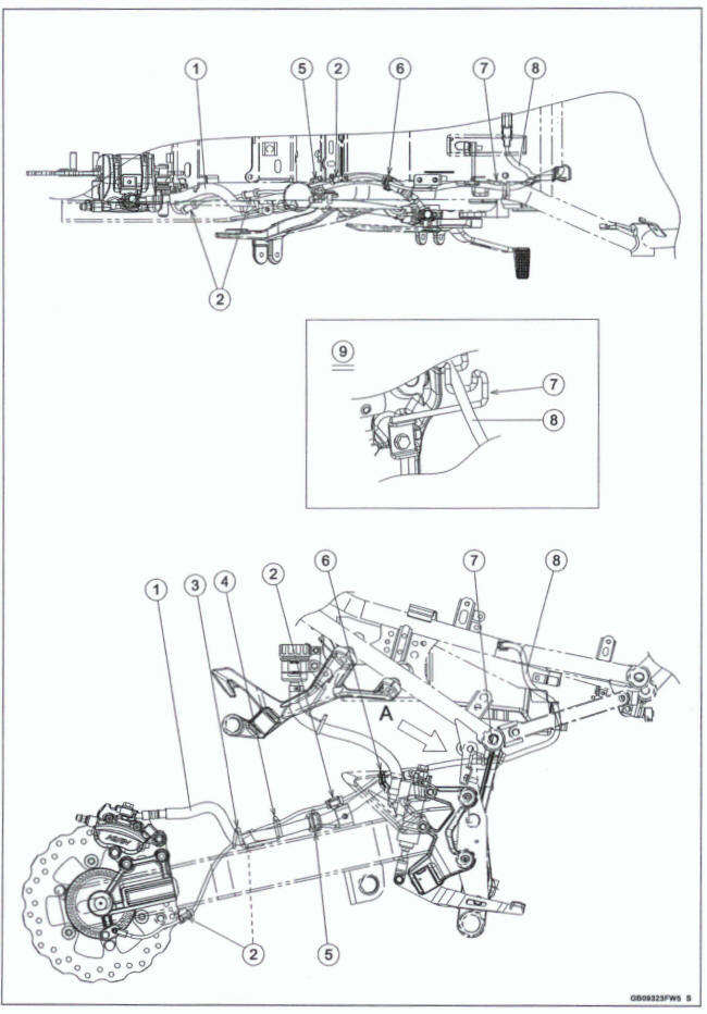
- Rear Brake Hose
- Clamps (Hold the rear wheel rotation sensor lead.)
- Run the rear brake hose into the guide.
- Run the rear wheel rotation sensor lead and rear brake hose into the guide.
- Guide (Hold the rear brake hose.)
- Clamp (Hold the rear brake hose and rear wheel rotation sensor lead at the white painted mark of the sensor lead. Position the clamp so that the open side faces inside.)
- Run the rear wheel rotation sensor lead into the guide.
- Rear Wheel Rotation Sensor Lead
- Viewed from A
ABS Equipped Models
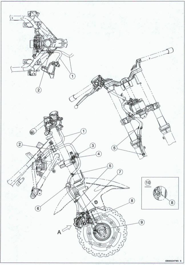
- Front Brake Hoses
- Clamp (Hold the front brake hoses.)
- Clamp (Hold the front brake hose.)
- Front Wheel Rotation Sensor Lead Connector (Install it to the bracket.)
- Clamps (Hold the front brake hose and front wheel rotation sensor lead at the white painted mark of the front sensor lead.)
- Clamp (Hold the front brake hose and front wheel rotation sensor lead.)
- Front Wheel Rotation Sensor Lead
- Clamp (Hold the front wheel rotation sensor lead. Face the open side of the damp to the rear side.)
- Front Wheel Rotation Sensor
- Viewed from A
ABS Equipped Models
- Rear Brake Hoses
- Clamps (Hold the rear wheel rotation sensor lead.)
- Run the rear brake hose into the guide.
- Run the rear wheel rotation sensor lead and rear brake hose into the guide.
- Guide (Hold the rear brake hose.)
- Clamp (Hold the rear brake hose end rear wheel rotation sensor lead at the white painted mark of the sensor lead. Position the clamp so that the open side faces inside.)
- Guide (Hold the rear brake hose.)
- Run the rear wheel rotation sensor lead into the guide.
- Rear Wheel Rotation Sensor Lead
- Clamp (Hold the rear brake hoses.)
- Viewed from A
Evaporative Emission Control System Equipped Models
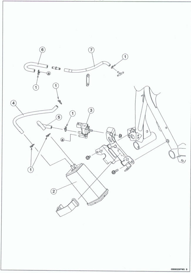
- Install the clamps as shown.
- Canister
- Purge Valve
- Fuel Tank Breather Hose (Fuel Tank ~ Canister)
- Purge Hose (Canister ~ Purge Valve)
- Purge Hose (to Purge Valve)
- Purge Hose (to Throttle Body Assy)
Evaporative Emission Control System Equipped Models
- Canister
- Purge Valve
- Throttle Body Assy
- Fuel Tank Breather Hose (Fuel Tank - Canister)
- Purge Hose (Canister - Purge Valve)
- Purge Hose (to Purge Valve)
- Purge Hose (to Throttle Body Assy)
- Blue Paint Mark
- Green Paint Mark
- Stick Coil #2
- Clamp (Hold the purge hose [7] and stick coil #2 lead at the green tape position of the purge hose.)

 Benelli Imperiale 400
 BMW F900XR
 Honda CB500X
 KTM 390 Adventure
 Triumph Street Triple S
 Yamaha MT-03
 Kawasaki Z400
 Triumph Street Triple S
 Yamaha MT-03